DSP-10 Software Radio
Hardware Page
back to n5bf/6
DSP-10
page
After the DSP-10 and Brickette themselves, the "official" boxes
from the project, I'm building a station by adding other hardware, some
of it kits, some of it my own development ("homebrew") and possibly
some storebought things where I don't want to spend the time and effort
on that particular functionality. For example, I'll soon be
buying an elevation rotator. I am not a machinest or motor maker,
and never will be. The stuff it rotates, and the stuff that
energizes what it rotates, and the form of that energy, well, that's a
different story. Also see plans.
The first additional projects are to increase the transmit power output
and the receive sensitivity at two meters.
2008
April 11 - 2 Meter Linear
Amplifier: CCI 875A
In the ongoing quest to see EME2 results in a single session, without
post-processing, and generally to make incremental station
improvements, I ordered a Model 875A
75 watt linear amplifier from Communication
Concepts, Inc.
2008 May 31
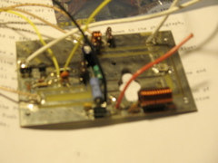
Started construction on the 875A. Worked about eight hours
and got through about half of the assembly, up to the point where they
say "time to take a break."
Started an "intended modifications" list:
- Select between Q2 and external key with an SPDT. Connect CR1 to
Q2 collector for normal operation, to ground key jack (i.e. to
Brickette) for external.
- Switch select between FM and SSB dropout for normal operation.
This is probably not necessary, 1/4 second is a fine unkey time for FM
as well as SSB/CW.
These switches might be discretes from some control circuitry (i.e.,
ethernet or USB) rather than physical switches.
2008 June 7
Continued 875A construction, reaching "Heatsink-Case Assembly" in about
two hours. Stopped after another hour with installation of the 10
Amp fuse in the fuseholder.
2008 June 11
Working, as always, towards a VHF QSO Party deadline, resumed work and
in about an hour was ready for first smoke. Everything looked
good on the first five minutes of applied DC power (without RF
drive). Noted the 3 W bias resistor drawing .17 A (as advertised)
and noted that it was hot! Used
the BK Test Bench 390 thermocouple to measure it at 90 C (200 F).
Did a cursory test to see if it was amplifying. Saw 35 Watts on a
Bird 250C before blowing the 5 Amp fuse on the Rig Runner. Moved
to a 25 A outlet.
Noted that, due to supplied parts in the RF sensing circuit, the unkey
was like FM, nearly instant. Don't like RF sensed keying to start
with. Made notes about how to remote this from the Brickette
eventually (see list on May 31. Estimated the correct value and
hunted around for the right capacitor to increase the unkey delay to an
appropriate value for 20 WPM CW or any SSB use.
Hooked up to dummy load and took data to find gain, compression, and
efficiency and entered it into Excel. (Converted to the upcoming
plots while posting this on 2008 October 21.)
Data taken: "DSP-10 setting" (144.200.400 CW), "in dBm" (ka7exm /
tap), "in Bird 5C," "out dBm" (ka7exm / tap), "out Bird 250C," "input
supply voltage" (Whattmeter), "input supply current."
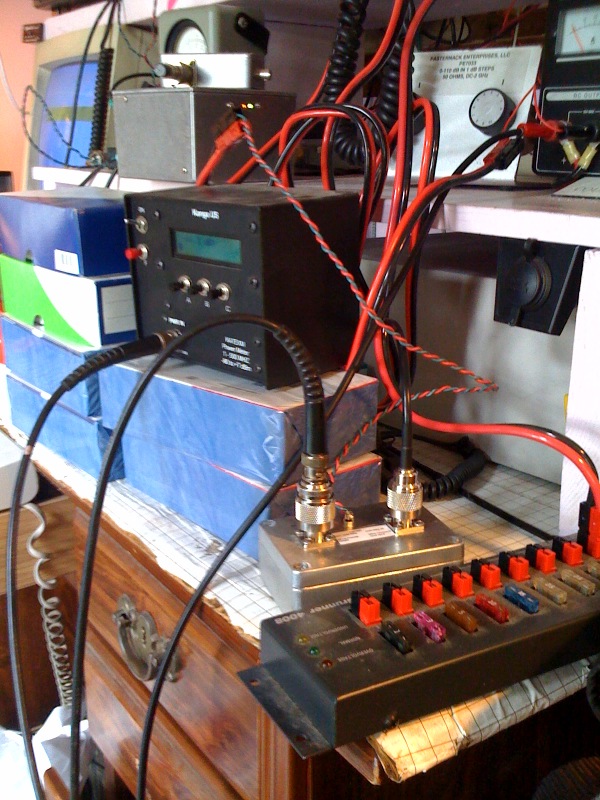
This is the hookup:
__________
_____________
________
_______
________ ____________________
|
|
|
| |
| |
| |
|
|
|
| DSP-10
|--->| Brickette |--->| 875A
|--->| Tap |--->| Bird |--->|
Heath Dummy Load |
|__________|
|_____________| |________|
|_______| |___43___|
|____________________|
|
|
____V_____
| KA7EXM |
| power |
|__meter___|
The amplifier is class AB1 with the gate biased by the above-discussed
bias resistor to about 0.6 V. More than the top 180 degrees of
the sine wave is passed through. The rest is clipped at the
bottom in order to increase RF output power. Output is
relinearized in a tank circuit consisting of C16, L4, C5, L5, and
C6. Coaxial traps, SF1 and SF2 in the design filter the prominent
3rd and 5th harmonics that result from this
clipping.
As for the large current in the bias resistor, when Q3vbe
> Q1vbe, 0.3 - 0.4 A flows in the supply circuit due to
the bias. Otherwise it's a few mA. Whether this happens or
not seems "slowly" random and changes from one power up to
another. For this reason, I leave the amplifier unplugged ("off")
when not in use.

This is a plot of the output/input data, against the calibration
formulas for the KA7EXM power meter (Test
Equipment for 2007 November 22).
Notes:
Output equals input up to setting 67 and gain is 0 dB. RF sensor
did not pull in.
On settings 68 and 69 the RF sensing relay chatters. No useable
output.
At setting 70 (on the order of 0.1 wat in) and above the amplifier
pulls in and amplifies.
Gain is 10 - 11 dB at power levels of interest. Not terribly
"linear." (Average 70 - 100 is 10.0 dB.)
1 dB compression point cannot be measured with this setup as the
Brickette limits first (around 3.8 W, as seen before).
DC to RF efficiency at setting 90 (typical) is 57.5W / ( 12.13V * 5.77A
= 70W ) = 82%. (Class AB1, as discussed above). At low
levels, efficiency can be very low, of course.
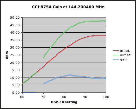
Notice that amplification is beyond linear. Thinking this might
be an artifact of the meter, I graphed up Bird meter data that was
taken simultaneously and found that the shape was the same. Here
is what I think is happening.
The amplifier is Class AB1 with the final biased at 0.6 V. At low
input levels like 5 dBm, no clipping would occur, so the amplifier is
Class A. This is not enough power to pull in the RF sensing
relay, but there would be much less clipping at 20 dBm where it does
pull in than at 37 dBm (5 watts) where clipping would be near
half. At lower powers, therefore, the amplifier is "less
nonlinear" and being more in Class A, has less gain. With rising
power levels, it approaches Class B (half cycle clipping) with higher
gain. This is seen clearly here. Unfortunately, I don't
currently have any more powerful driver with which to extend the curve
further.
References I found on Class AB1 (like http://en.wikipedia.org/wiki/Electronic_amplifier
indicated that the higher numbers (i.e. AB2, etc.) indicated push-pull
transition with less non-linearity. They did not discuss
single-device AB circuits but clearly a push-pull circuit with only
"push" as this one is, would have poor transition, thus the lower
number "1".
Max 875A output power on this plot is 62 watts. Rough sensitivity
to supply voltage is:
Vsupply Pout
11.9 55
12.4 60
13.6 70 @
8A
14.5 80 @
8.6A
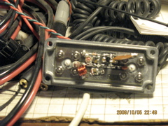
2008 June 12
Tried to increase drop out time by putting two 2.2 uF in parallel with
C4 (470 pF). No noticeable difference.
The 10-15 uF tantalum makes a 0.15 second drop out time, not 1.5 second
as noted in the instructions.
Moved C14 (10 uF) over to be parallel with C4. Made the drop out
0.1 second. Not enough.
Put C14 back.
Put 47 uF across C4. Delay of 1/2 to 2/3 second too much.
Put two 47 uF in series across C4. Delay of 1/4 second perfect.
Closed lid and put online.
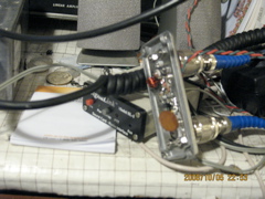
2008 June 13
Opened and cleaned up.
2008 June 14 - 16 Contest
Day!
Made the largest number of QSOs in a party to date, 43. Only 5
grids this time though (no CM94). People were calling me who I
couldn't hear. Need better receive sensitivity.
2008 July 9
Tried EME2 "QRO" expecting that since I'd done it with about 6000
points at 6 watts, I should be able to see something at 100 or so
points at 60 watts. Tried several such sessions and saw
nothing. Posted a report with questions to the list. No
replies.
From May 12 to October 19 made lots and lots of notes of theories to
test and other improvements to try when I "have time."
2009 February 27 Did
a
brick-on-key test on the 875 2 meter amplifier. Putting 60
watts into
a dummy load, after 30 minutes the part was at 81C and the fins at
55C. After key-up for 45 minutes it was back to ambient.
2008
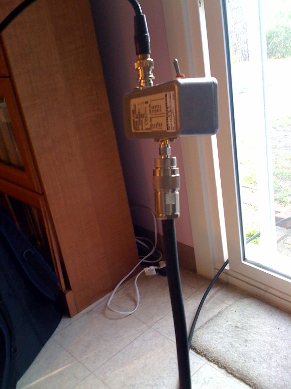
September 17 - 2 meter receive
preamplifier
Began research on preamplifiers and sequencers and drew a
picture of how I wanted to hook up an in-shack preamp for the current
application. Although it would give better performance to have
the preamp mast mounted, I wanted to start with it in the shack so I
can keep an eye on it and fiddle with it. I am willing to eat the
1-2 dB cost of doing this for now.
Placed three orders.
A Down East Microwave VHFLNACK-2N,
the kit version with two N-connectors on it. As advertised, has
15 - 18 dB gain, noise figure < 0.7 dB (50K) and can be tuned up for
138 MHz, 2 meters or 1.3 meters. Interestingly, Down East, which
used to be in New England (thus the name) now ships out of Florida and
has data sheets from New Jersey.
A Tohtsu
SPDT UHF Relay from Surplus
Sales of Nebraska.
All the interconnecting cables and adapters that my diagram said I
would need from Mouser.
These were $40, $80, and $160 respectively. Adapters are
expensive.
The Brickette has the ability to switch a separate receive line for
cases like this but I wanted to switch both Brickette and 875A out of
any direct connection with the receive-only preamp.
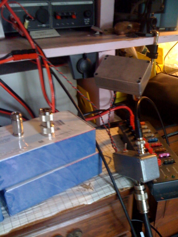
The sequence that the DSP-10 already does is not everything that is
recommended. It usually goes:
power off preamp
throw relay
transmit RF
with something like 30 msec between each stage.
The DSP-10 does throw the relay first, well before transmitting.
I ganged the Tohtsu relay off of the Brickette PTT-ground sense output
and did not switch power to the preamp, just leaving it on all the time.
As discsussed above, I'd like to someday switch the 875A directly, not
through RF sensing. It is this level of "fixing" all in one
"project" that keeps anything from ever getting started or finished, so
I just hooked up for what I thought would be safe and tried it.
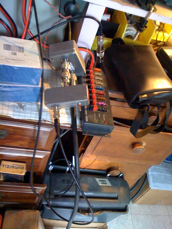
2008 September 24
The Mouser order came first on the 23rd. When
the Tohtsu relay came on the 24th I went ahead and re-cabled
everything, wiring up the relay DC to a power plug and a phono
connector to go down to the Brickette. Of course, the preamp was
not in the circuit yet since it had not arrived yet, much less been
built.
As always, I hooked up the relay coil backwards (maybe because I was
doing it during the first Obama / McCain debate) so that merely
plugging the cable into the Brickette caused the relay to key.
Duh! I guess there's no point in triple checking. Rebuilt
to where it worked right. The hookup is like this:
NC
RCA Blk RCA ^
BNC Ylw UHF UHF Red UHF UHF
Grn UHF 100' RG-8
___________
__________|__
________ ________
__________
________
|
|
| rx
| |
|
| |
| |
| |
| DSP-10 tx |----->|
Brickette |----->| 875A |----->|
Bird |----->| Tohtsu |<----->|
2M12 |
|_______rx__|
|_____________| |________|
|___43___|
|__________| |________|
^
| phono grn PTT gnd
^ ^ |
|
-------------------------------------------| | |
|
__________
DC |
| BNC Blu N
| DEMI | N Blu UHF |
----------------------------------------| Preamp
|<----------------|
|__________|
Colored BNC cables are used on purpose. This has already saved me
from misunderstanding, hooking up incorrectly, or damaging equipment.
Originally I had wanted to drive a PTT circuit direct from the DSP-10
to do everything, but the relevant output from the DSP-10 is +5V for
TX. This is converted to ground by an NPN circuit in the
Brickette, intended for a relay driver just such as this.
On the first test, the relay closed at 13.44 V drawing 169 mA, roughly
as advertised. In the process of debugging this seemingly trivial
function, threw out a yellow phono cable that I'd had for years.
This might well have been the one that caused all the Argonaut powering
trouble at FD02.
It was certainly the same color. Now a green one is in use, as
noted in the diagram above.
2008 October 1
Opened up the box from DEMI and checked in the preamp. Mounted
the connectors, board, and C9.

2008 October 5
Viann was in San Francisco on business. Resumed construction
while listening to everything playable at http://keithkirchoff.com/composition%20works.html
. (I'm told he and his wife have visited our church!)
Installed C8 in the C7 place and broke it getting it off. Now it
was 50 nF rather than 100 nF. The only replacement I could find
was a big disk ceramic about 1/2 inch in diameter!
Even counting this setback, construction only took two hours including
the PowerPole.
First smoke went fine. Hey, the 78L09 regulator and gasfet
amplifier parts were installed correctly. Guess not everything goes wrong.
Vdd was 3.9 V indicating another parallel source resistor
was needed. Added this, marking it as "R10" in the
schematic. This made Vdd 3.1 volts at 56 mA,
approximately as expected.
Put the preamp in the receiver path, with the box open. The noise
floor came up from -142 dBm to -125 dBm. Good --
amplification. Hooked up the calibrated noise source and started
tweaking around with C1 and C2. Got the noise figure down to 700K
at 20 dB gain with the lid off. Put the lid on and the noise
figure was 260K. Good, but not as good as expected.
Tweaking around some more didn't help. The tuning capacitors
looked broken.
Tried listening to N6NB/B in DM05. The preamp seemed to help but
reading the long term integration "yellow line" was inconclusive.
I know the convention that a straight piece of wire through a core
counts as one turn. There wasn't a core on this L1 so does just a
straight piece of wire count as one "turn?" 3-1/2 turns for 1.3
meters, 4-1/2 for 2 meters and 5-1/2 for 138 MHz, it says. Spent
a bunch of time trying to figure out whether I had 3-1/2 or
4-1/2 Tried calculating inductance of the coil from places
like http://www.daycounter.com/Calculators/Air-Core-Inductor-Calculator.phtml
and at some length decided that I understood how the input tuning
network worked impedance-wise. This would be crucial, I decided,
to getting the noise figure low and selectivity reasonably high.
(I don't have any intermod on the DSP-10 (although loud stations do
overload it) because I'm using a narrowband radio on a narrowband
antenna. I don't want a preamp to mess that up.)
The coil diagrams in these instructions aren't as clear as on the 875A
or the DSP-10 itself.
2008 October 6
Made up a new inductor with plus one turn from some #22 coil
wire I had laying around -- not the same size as the #18
original. Does that make a difference electrically or just
mechanically? Tried it. Wasn't able to peak it at 144.2
MHz. Went back to the original. The capacitors were really
broken now. Ended up with a "lid on" noise figure around
350K. This was getting worse.
Placed another Mouser order for ten 0.1 uF chip capacitors (C8) and ten
1.8 - 6.0 pF trimmers. Didn't want to wait another week if one, or eight of
these got broken.
2008 October 11
Checked in the Mouser order. The new trimmers looked exactly like
the old ones (except both are surface mount) but they held up much
better, possibly because I was much more careful with them.
Replaced C1, C2, and C8.
I had decided that I would settle for a system noise temperature
(including DSP-10 after preamp gain) of 100K if I could get
there. This plus 1.5 dB in cable loss to the antenna would still
give me a factor of ten better in receive performance than I'd had so
far.
Hooked up the preamp to the KA7EXM power meter with the input driven by
the DSP-10 through a JFW 20 dB pad. Peaked for gain ended up with
+0.4 dBm out for -24.3 dBm in. 24.7 dB gain, yikes! This
gave a lid-off noise figure of 660K.
Next, hooked up the calibrated noise source and very carefully peaked
the "whole bandpass noise level" for "on" then very carefully nulled
for "off." This gave a lid-off noise figure of 330K. Put
the lid on and did a coarse re-measure. 87K! Yes!
Tightened the screws and declared this done. Back on the
power meter, measured the gain carefully. Using inputs over a
range of -54 to +13 dBm, decided to use 22.0 dB for the gain and -4 dBm in
as the 1 dB compression point.
Hooked up the calibrated noise source and did full-bandwidth noise
averages over 60 seconds, on and off several times. Settled on
the following calculated values:
case
K dB
DSP-10 alone
3200 10.8 *** better than measured on 2008 September
6. Possibly because this is a good jumper cable.
system
71 0.95
preamp
only 51 0.7 inferred from
amplifier chaining equation, but exactly as advertised
station 200
2.2 estimated, based on 1.5 dB cable loss to antenna
Went off to N6NB/B and did several "in" and "out" tests.
In both cases, LTI would give the beacon at 7 dB above the noise floor
after about 1000 integration points. Also, in both cases the
beacon was easy to copy, Q4. This was an unusually good
propagation night apparently. Went off and pondered why the
preamp wouldn't help in an LTI case.

2009 January 16 Spent
the four day weekend
putting an HF antenna back up that I don't need until November
Sweepstakes (if
then). Discussed at Contests.
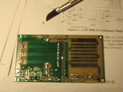
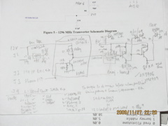
1296RSU
Converter
2009
February 23 Don, AE5K, posted news of a group buy
of microwave transverter kit parts to the DSP-10 list. Realizing
that this was one of those now-or-never moments, joined the 4-State
Microwave list and expressed interest in a 1296RSU,
that is a 1296
converter with 1152 LO. "Right Side Up." W1GHZ was
supplying the boards from his design. Resisted the temptation to
buy several other bands worth, pending how this went. By early
March the group buy was underway. Bought an extra LO thinking
that I might adapt it to 576 MHz (1152/2) for 432 later. (I don't
know what any of the four states are, but in this age of the internet
it doesn't matter, except for "local radio.")
Note Originally the schedule said
this would be 2-3 week's effort and I'd probably get to it sometime
around May. By October I had things basically working, but it
wasn't working as a radio, at least beyond a few hundred feet from
home. By the time of the writing of this note, 2-1/2 years later,
I had revised all the requirements, indefinitely postponing things like
1260 satellite band choice and LO frequency agility, and adding things
not initially intended, like a preamp, two stages of post amp, a
filter, a control system, a relay, and a "big" box. This is kind
of the way these projects are intended to be, start out with something
little, work on it at various levels until it works, and learn lessons
along the way. It works like a radio now, but the story is long
and tortured, about fifty times as much effort (and as we'll see,
around twenty times as much money) as originally imagined. (Note
that I said "imagined" as opposed to "planned" or "conceived" because
stuff like this is really imagination driven.)
But...
"Every Chip" means something.
For the same money and a lot less time I could have a better rig than
this, but any operation I did on that rig would never compare to the
thrill of working somebody (or equivalent) on something I put together
and got working myself. It's really just not the same
thing. And a storebought rig will probably never do EME2.
(Yes, I realize I could do it in audio <-> soundcard mode, but,
no.)
It's the Journey....
(10/23/11 during completion of the
story.)
2009
April 22 Took time away from study of Cocoa to log in my 1296RSU
order.
2009 July 6 1296RSU
construction begins. The unlikely goal is the ARRL UHF
Contest, August 1-2. Inquired on the 4-States list
about enclosures. Checked in parts.
2009 July 12 Get signal
generator and oscilloscope going. Put down the capacitors on the
LO board.
2009 July 13 Consulting
the web for theory,
schematics, and parts placement,
2009 July 17 Finish most
parts placement. Lesson (re-)learned: Solder parts through
holes first.
A major review at work 2009 July 30 forestalled any progress for two
weeks.
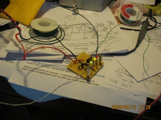
2009 July 31 Put on
PowerPole for supply and did first smoke test. Regulator and MMIC
output voltages look good. Oscillator running at 64.00021 MHz, 15
dBm. The input to A2 was 192.001 MHz as expected. Poked
around trying to measure other frequencies and signal levels.
Downloaded the manual for my MXG 9802
signal generator and frequency counter to see how much signal it
wanted. Decided I needed a better probe.
The UHF Contest came and went without note.
Went on vacation.
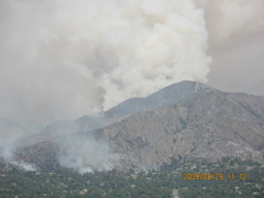
The nearby Station Fire
occupied us for several days at the end of August and beginning of
September.
2009 September 7 The new
goal is the September 12-14 ARRL VHF
QSO Party. Cleaned up work area again. Listed remaining
steps. Need to specify and order a box and spacers. Need to
switch 8 VDC for transmit / receive. Posted questions to the
4-States list. Placed an order for a Hammond 838 ND box.
Not a good
choice, but it would eventually be made to work. Drew some
pictures about how the boards would be placed and connected. None
of this worked out as pictured.
2009 September 8 Populated
the LO parts on the 1296 board. Went on a search, then a trip to
Radio Shack for some RG-174. Finally found enough in a tangle in
a box in the garage at home. Using a TNC panel mount as a probe,
and grounding it to the ground plane, was able to measure 1152.0023 MHz
at the output of A5. Extrapolated power measurements with my
power meter (that goes up to 500 MHz) turned out to be meaningless.
2009 September 11
Received the Hammond box. Populated the receiver board.
Blew out the current circuit of my Whattmeter
due to a short on the converter board. Cleared the short.
Nothing else broken. Whattmeter still works but reads 0
Amps. The cumulative power function still works. (Can
monitor for 36 seconds and multiply to estimate average current.)
Installed the mixer carfully. Ready to test at noon. Output
of A5 still reads 1152.0001. With no antenna on the HT, get 30
over 9 on DSP-10. Overloads with HT antenna. Extrapolating
from the KA7EXM measurements, decided that DSP-10 drive should be about
80-86 (around 0 dBm) for ~16 dBm output.
Set up the DSP-10 for "band E" with this converter LO frequency and
conversion gain. Asked the list what I should use for
"transverter gain" in UHFA.CFG. Guessed about +23 (SGA-3586Z) -3
(splitter) - 7 (filter) - 7 (mixer) = +6 dB. Talked to and from
the IC-T81A on FM on 1296.100
with good audio both ways. Posted success to the list.
Frequency measurements look good. Power seems reasonable, lacking
precise measurements. See a little bit of motion on the Bird with
a 2.5K slug indicating perhaps 0.02 watts, 13 dBm. Still need to
work out T/R switching and box.
Spent an hour designing a 8 V T/R switch and indicator circuit.
Take a list and $20 to Radio Shack.
2009 September 12 Build
up the 8V switching T/R circuit. Liked it so much that I made it
into my e-QSL
card.

The LEDs indicate 8 V supply:
Green: receive;
Yellow: LO;
Red: transmit.
The circuit takes T/R from the DSP-10 and uses 2N3904 and 2N3906 to
switch the 8 V.
1230: Set up the new drill press (from a Harbor Freight special via
KG6JIS) to drill holes in the box.

It was a joy to use a drill press. Drilled 18 holes perfectly
with only one error due to poor planning. This took two hours and
no swearing. "Measure once, cut twice." Yeah, yeah.
While working, listening to the VHF contest on 144.200. People
(K6TSK included) are talking about moving to 1296.100 but it's not
clear they would hear me at +13 dBm to a discone. K6TSK was also
advertising his Friday evening 23 cm weak signal net.
"Final Assembly" underway by 1700 local but was asking the 4-States
list for advice on how to lay out a bigger box with more little boxes
in it.
All the connector installations went well. Had to move the LEDs
down a little to get into the perfect holes. Starting to actually
place things in the box on the spacers and wire them up, it was
determined that this was nowhere near the right size and shape box for
this. I lost one to two days effort overall messing around trying
to get things in and working all at once.
Lesson Learned: Make up a
cardboard box with cardboard boards and strings for wires and build it
up to see how the clearance and things will go before ordering or
drilling or mounting anything. This would have taken 2-3 hours,
not 1-2 days, and I'd be happier with the result. As an
alternative, just put things in a box that's way too big, but that can
have it's own electronic issues. (In retrospect, that's what
amateur and professional prototypers do. We call it "Technology
Readiness Level - 4.")
2130: Put in last screw. Everything seems to work except
the 64 MHz, so, no radio. Took out the LO board and turned it
around. Rewired everything. Worked, except with the lid on,
so, no radio.
The LO board doesn't even fit in the inside dimension of the box.
It has to be jammed in with a little diagonal.
2009 September 13 Have
worked and heard my local HT but that's it. Scanned around for
birdies. Hearing second-long pulses in groups of three.
Went to OSH
for some hardware to remount the LO board again. Put on the Bird
meter. Needle barely moves. One division is 50 mW.
Key down or key up gives 20
mW. What's that?
Recabled everything to 2 meters. Tried to work K6TSK on 144.200
but he
didn't respond. Worked a few others. Set back to 1296.100
and beacon CQ on CW while eating supper. No responses. Set
to FM and had KG6GXW sit at the radio while I drove around with the HT
(IC-T81A with Diamond SRH-999)
at 0.1 W to determine FM range. About 100 meters, 200-300 meters
in some directions. It's a hilly neighborhood.
2009 September 14 Tried
listening for N6XQ beacon: 1296.329 DM12jr, San Diego, CA.
18 W to 4 loopers @ 330 true. While hiking in the hills 1000 feet
above here my HT scanner has stopped on this signal though it is 150
miles away, but that was years ago. Wonder if it is still
there? Nothing heard today. Well, I thought I saw something, but when I
disconnected the transverter and terminated the input on the DSP-10 it
was still there. An IF birdie.
2009 September 15 Found
oscillator quitting during the night. Mechanically
sensitive. Opened up to investigate and fixed cold solder joint
on crystal ground. Now works dependably.
For the next several days would see things in the spectral display when
I was out of the room. Finally caught some. Some of it was
the microwave oven. Some of it was unknown, but clearly not
amateur activity on 1296.100.
2009 September 18
Measuring with frequency counter, saw a consistent output of
1460.3. Tried to calculate how that could be happening.
1460.3-1296.1 = 164.2, not close to 64 or 144 or multiples of
those. Don't know. Listened for the Friday evening
net. Nothing.
2009 September 19 Discovered
that the problem was a shorted inter-board cable. Did a whole
bunch of rework until I had 1152 LO and 1296.100 output again and the
receiver noise level went up and down with RSU power on and off.
This
involved cutting an SMA connector off the board and mounting a new one
on the other side. See "Lesson Learned" above about layout.
Threw away some problem cables that I should have thrown away years
ago. Haven't heard the "three dashes" signal since.
While doing this, put the HT on the discone and scanned the entire 1240
- 1300 band for activity. Nothing heard. After some
investigation, decided that the connectors on the 9913 to the discone
weren't any good. Put the Diamond
SRH-999 on the HT and resumed scanning. In addition to some
birdies (the 1244.350 of which was traced to DSP-10 digital
electronics!) it ultimately stopped on some repeater activity.
Reverse engineered the PL to verify that I could hit it with one watt
and determined from QSO context that it was on Palos Verdes, some 30 km
away. So that's a baseline. With an indoor Diamond
SRH-999 at one watt, I can at least hit an FM repeater 30 km
away. Was barely able to even hear them on the discone, at least
40 dB down, so the discone
system needs repair.
The Sabine
Noise Source has a factory calibrated ENR of 20.10 dB at 1296
MHz. Receive noise in the passband increased 2.9 dB when it was
on. This gives a noise figure of 20.4 dB, about 30,000
Kelvin. From the literature on this line of transverters, I
thought it would be more like 6 dB. I could have 14 dB loss in my
hookup. Wrote W1GHZ about this. His reply was:
"I've not actually measured a 1296 RSU noise figure, but several of the
others
were around 6 dB. there isn't any excess gain in that
transverter, so
noise figure goes up quickly if gain goes down"
This is inconclusive but the system is certainly a candidate for an
early low noise amplifier.
Measured passband noise with transver on and off. For 1200
averaging: On, 35.22 dB; off 31.82 dB.
Used the HT to do some discone measurements and decided not to use it
until I could make repairs. Set the 1296RSU box on its front and
stuck the SRH-999 straight up out it's back. This is vertical
polarization. This is indoors. The seeming odds of hearing
anything
just diminished. Monitoring this way, continued with other
activities, HF and non-ham.
2009 October 3 Am I "hearing"
(i.e. "seeing") something real?
The spot at 0004 is me in the driveway without HT antenna.
The line before 0050 is me in the driveway with the antenna.
The CW stuff is sent so I could hear it on the antenna in the driveway
without bringing the rig in.
The line at 0435 could be net activity. I was at work (left home
at 0115) and wasn't able to listen.
There have been other falses, but this wasn't iPhone activity because I
had the iPhone with me at work.
It was about the time Viann got home from work, but we haven't heard
the GZ'one (Verizon) ones on here.
Might have been microwave oven (likely....)
There have been other falses - radar like on the roof antenna, but not
on the SRH-999 in the house like this.
There were also falses when it was somehow on 1460 but those don't
count now.
If this is the net, it is the first time I've seen/heard anything on
here that wasn't me.
Inconclusive.

2009 October 7 0304 UTC
Heard "K6" on CW about 1 kHz up from 1296.100.100 CW. No other
radio was on so it had to be from 1296. Later heard CQ but didn't
copy the call. Tried my own CQ. Nil. They were weak
enough they could have been imagination in noise. Contest
operators know about imagination in noise. This was at the time
of the 2 meter San Diego weak signal net (Wednesday evening local).
2009 October 10 Fun as
this is, I'm not hearing anything on 1296. Return the DSP-10 to
144.200 until I can do something about an outdoor antenna. So far
I'm 50 hours into this "2-3 week's of spare time" project.
WA5VJB
"Cheap Yagi"
2009 November 14 W7PUA suggested I should put up a medium
gain antenna. Browsing my brand new 2010
ARRL Handbook I found just the thing on pages. 21.69-72, "Cheap
Yagis by WA5VJB." This can nearly all be built from hardware
store parts.
2009 November 20 Placed a
DigiKey order for connectors to
repair the 9913 coax, N to SMA jumpers, and an SMA connector with which
I'll attempt to make the driven element feed. Over $100 into this
$15 antenna project so far. (Granted, it's not all for the
antenna itself.)
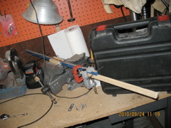
2009 November 21 Trip
to OSH for
wood, wire, and paint. Another $26.29 into this $15 antenna
project and this is all
antenna related, though I did get "extra." ("... always get
extra.")
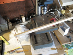
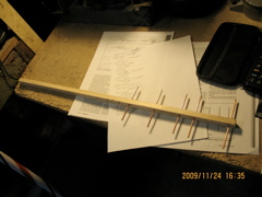
2009 November 24 Construction.

2009 November 25 DigiKey order arrived.
Installed connector. Load tests.

A. Found the initial resonance around 1260.
B. Snipped the 1/8 inch overhang on the driven element.
Resonance seemed to drop to 1240.
C. Moved the center conductor feed point 1/8 inch further from
the boom. No change.
D. Tried to cut 1/16 inch off tip of driven element, got 1/8
inch. Resonance about 1255.
E. Bent driven element forward a bit. Resonance about 1240.
F. Bent driven element backward a bit. Resonance about 1240.
G. Re-straightened and cut off 1/16 inch. Resonance 1280.
H. Moved center conductor feed point back to original
position. No change.
I. Cut off another 1/32 inch. Resonance between 1290 and
1300. Ship it!
1600 local, up on the roof
installing below the discone. In
retrospect, I would have made this a rear mount, not a center mount.
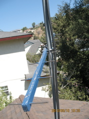
The 23 cm yagi is about 8 meters up (about 1 meter above roofline) and
fixed at 135 true - San Diego.
(Put the discone on the RG-8 recently retired from 6/10 dipole service.)
Went in to test. The inside N connector fell apart trying to plug
into the Bird. Began the replacement process. Buggered the
center conductor. That's why I ordered three replacement
connectors. Second try succesful, first connector in the
trash. Connector is a snug fit. This is finally the right
one!
Made power measurements. Resonance unchanged. Estimate 2 dB
cable loss
from flattening of return loss curve off resonance. That would
mean 22 dB system temperature, estimated.
The outside N connector is in better shape, but it's also the wrong
type. Decide to bring it in and replace it too.
Final loading unchanged.
Clean up then do basic tests. Still talks to and from HT.
Puzzled for a while why RF levels were so low. Somehow the DSP-10
RF gain was down to 82. Back at 100, all worked as before.
Remeasured passband noise with transverter on and off. For 1200
averaging:
On, 38.62 dB;
Off 32.30 dB;
On with terminated input, 36.70 dB.
Noise floor (with
conversion gain) seems to be -154 dBm (9.4 Hz bins). Encouraging
that "on" noise is higher than before. Maybe I'm seeing something
out there.
The antenna adds 12 more hours to the total effort.
Notes for future: Can measure cable loss by using Bird at both
ends, or measuring NF with and without. When it comes time to
upgrade, I should do this to evaluate the upgrade. Down East Microwave has
preamps and amplifiers for this band that will fit with this.
Those will be the next steps. Architecture (antenna mounted?
etc.) is unclear. Ultimate antenna is a 1.2 meter dish on az/el
mount, but that's a ways off so I'm monitoring with this antenna until
then.
2009 November 27 Listened
for the local 1296.100 net at 2000 local. Nothing before, after,
or during. Called some CW CQs, nothing. Maybe they're off
for the holiday. Maybe I'm not hearing anything.
Thought I was seeing the DM12jr beacon on 1296.329 then re-rediscovered
the DSP-10 internal birdie near that frequency, so, no. Nothing
heard.
Doubtless it's a quiet band....
2009 December 5 Listening
for the net at beam 150 true. Heard two voices, one identified as
KM6RMG, the other was a deeper voice, didn't copy ID.
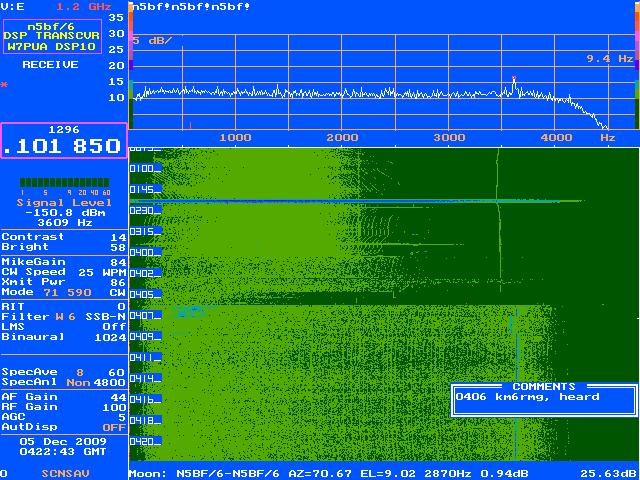
A few minutes later heard some CW. Fumbled at the controls and
did not copy it, but based on
later net activity and the time, it was probably K6TSK giving a final
call.

This was the first reception of signals on 1296 not generated by
me. Not booming in. Need some help....
2009 December 19
Copied the net again. Heard one distinct voice on SSB twice and
guessed it might be net control K6TSK but did not copy a call.
When he called on CW at 0430Z it was definitely K6TSK but he did not
respond to my QRPpp replies.
DEMi 23 ULNACK
- 23 cm Preamplifier
2010 January 29
Replanned
and decided to put off the az/el rotator for another iteration (and
until it stops raining for a while). Decided instead to take the
1296 RSU and add to it until I had a working 23 cm station. As
this will cost some money, if I finish before I have money saved up for
the rotator, I'll work on software, which is the other nagging thing on
which I need to move out.
23 cm stuff from Down East
Microwave:
- A 23ULNACK
0.4
dB preamp (which may not have enough gain to overcome the whole 20 dB
NF of the 1296RSU itself, but which will be a starting point and a big
improvement in any case).
- A 2330PA 50 mW-in 35 W-out
amplifier. The 1296 RSU only does 13 dBm (which I haven't been
able to measure very well) but 20/50 * 35 = 14 W, so I should be able
to get at least 10 W out of it, which should be quite workable.
One of these days I'll do another project to boost the 1296RSU to 50 mW
output somehow.
- An ABPM (All Band Power Meter) so I can get
better qualitative power measurements.
- A Tohtsu CX520D so I can
cable it up into a transmit / receive system, and a Bird 50K (1.1 - 1.8
GHz, 50 W slug) from RF Parts so
I can see what I'm doing on the output end.
There will be another order for cables and a box in which to re-box the
entire unit later.
2010 February 5 Checked
in the Down East and RF Parts orders.
2010 February 20 Started
a
cardboard box model of a new container for the 1296RSU. Decided
not to
do that but to just get a box that was big enough with reserve and
repackage it with a different T/R switching strategy. Placed a DigiKey order for the box and some
cables I will need (to be diagramed later when I actually hook it up).
2010 March 22 Start into 23
ULNACK kit by reading the
directions and checking the parts list. All present.
Attached the connectors and soldered down the board.
2010 March 26 Did all
assembly up to the point where it was ready for a PowerPole(R)
power connector. About two hours.
2010 April 1 Attached the
PowerPole and pigtail and plugged into strip for smoke test.
Immediatly blew a 3 A fuse. Discovered that the 13.8 VDC input
was soldered to the ground via of the PPS-1 Single Stage Bias Power
Supply, not the B+ input. Every stage of every project seems to
cost at least one RIGrunner
fuse!
Set the preliminary DC bias to 600 mV as directed then installed
R2. Adjusted the bias for drain current of 17 mA (which was
"between 15 and 20 mA"), calculating the C4-R5 junction voltage needed
to produce this current. This resulted in a gate bias of -234.4
mV. There was no trouble doing any of this. The directions
said that if the DC voltages were right the thing would just work as
advertised, with perhaps only a tweak to L2. This sort of claim
is always hard to believe.
Current is 21.0 mA at 13.81 VDC. That seemed about right.
Mashed L2 up tight axially (but still round radially) and put the lid
on for testing.
2010 April 3 Did labels
for this and the DEMi VHFLNACK
built in the fall of 2008. Where does the time go? I swear
I spend way too much time at work!
Labels took about an hour then I planned the suite of noise figure
tests over lunch.
The initial on-the-air monitoring configuration is going to be this:
__________
_____________
___________
__________
________
|
|
|
|
|
| |
| |
|
| WA5VJB
|--->| 50' 9913 |--->| 23 ULNACK |--->| 1296 RSU
|--->| DSP-10 |
| 8-el beam|
|
|
|
|
|
| | |
|__________|
|_____________| |___________|
|__________| |________|
^
|
13.8 VDC (7-16 VDC)
I know that things would be better if the preamp were up at the
antenna, but I don't want to switch up there or send power up there and
I want to keep my eye on the preamp for a while, so it will be indoors
for now. We'll measure it both ways and dream. The box
comes with weatherproofing materials.
The goals of the measurement campaign are;
- Check that the RSU-1296
still works like it did in November and still has a high noise figure.
- Check that the WA5VJB
beam hasn't changed.
- Estimate the noise figure and gain of the 23 ULNACK
- Estimate the L-Band loss of the 50' of 9913.
- Measure the difference between preamp in indoor and outdoor
configuration.
Today is receive only. After verifying that the 1296-RSU still
works, the T/R control will be disconnected. (The transmit end of
the project is upcoming.)
So just to give an idea of how "real time" something like this can
be, here is the original plan:
0. Make sure the 1296 RSU still works.
1. Retest 1296 RSU for noise figure as is:
20 V -> Sabin
Noise Source -> RSU -> DSP-10
2. Test 23 ULNACK for noise figure:
20 V -> Source -> 23 ULNACK -> RSU -> DSP-10
3. Measue noise figure with roof cable in intended configuration
(detach cable from antenna, bring in through open sliding door):
20 V -> Source -> 9913 -> 23 ULNACK -> RSU -> DSP-10
4. Connect back to and reorient the antenna
5. Listen - Test - See if I can find a signal source that I don't
own.
At 1435 local, with the plan in hand, got started with Test #0.
With T/R from DSP-10 hooked up, talked to the IC-T81A HT
and listened to the 1296RSU talk back on FM. Everything was still
OK.
Hooked up the series power supplies jig that I have to get 20 VDC into
the Sabin Noise Source. Did this wrong, of course, by hooking up
the +8 V to the +8 ground and blew another
3 A RIGrunner
fuse. Reconnected correctly and set the voltage to 20.00 VDC
using the BK-390 Test Bench. Getting low on 3 A fuses, but have
some 5's left.
I can hear microwave oven (adjacent kitchen) hash on the 1296
RSU. Messed with RF and IF cables to see if I could reduce
this. Determined that the QRP TX loopback to the DSP-10,
unterminated, was picking this up (on 2 meters) Waited for Katy
to finish cooking her lunch anyway.
Set up for Test #1. Found that the noise source on/off made about
3 dB difference. That's about right. Went to one minute
integration for the real measurement. Got 19.7 dB noise
figure. Last September got 20.4 dB. That's close enough.
The calculation in powers and ratios is
F = ENR/(Pon/Poff -1)
In this case Pon / Poff = 31.61 dB - 28.38 dB (total noise in the 4800
Hz DSP-10 passband) = 3.23 dB = ratio of 2.10.
Source ENR at 1296 is 20.10 dB = ratio of 102.
102/1.10 = 92.7 = 19.7 dB
The data and results for each of the test calculations are detailed in
a table below.

I can hear the iPhone (that made this picture) on 1296. I bet
that's direct.
Now the moment of truth, Test #2.
Power the preamp on - receiver noise goes up 4 dB. Good.
Switch on Noise Source, receiver noise goes up another 17 dB.
Whoa yeah! Now we're hearin'.
Calculate the system noise in this configuration to be 3.0 dB.
Google around for a while and try to solve Frii's equation for preamp
alone. Hmmmm. I need a preamp gain. Can't determine
both gain and noise figure independently from one measurement.
Checked my notes from the VHFLNACK.
Sure enough, I used the KA7EXM power meter to measure low levels out of
the DSP-10, then used the DSP-10 transmitting into the input of the
preamp to find its gain and 1 dB compression point. The KA7EXM
meter only goes to 500 MHz, we already know that. Considered
building the DEMi ABPM (All Band Power Meter) at this point.
Although it would work at this frequency it would not calibrate
precisely enough for this measurement (~ 1 dB) and in any case I don't
have any way to calibrate it
at all, aside from the KA7EXM meter and
that only at lower frequency.
Studied the "power meter linearity" plot at 2007 November 22 of
TestEquip.html#KA7EXM_Power_Meter.
Noting that at 1 GHz the meter was pretty linear (10%) if it was reading over -60 dBm but that -30
dBm would really mean about 0
dBm and thinking I might be able to get a few good input and output
points in that range, decided to try it anyway, it was the best shot I
had. One should stop around 0 dBm on the preamp input.
The 23 ULNACK instructions say noise figure < 0.5 dB, gain > 16
dB. OK.
Devised:
2.1 Preamp Gain Test
DSP-10 -> RSU -> KA7EXM to get input levels.
DSP-10 -> RSU -> 23 ULNACK -> KA7EXM to get output levels.
Audio stopped coming out of the DSP-10. Ended up rebooting it for
the first time in months. All OK once again. Seems to be an
unrelated malfunction.
This is the data:
DSP-10 preamp
in preamp out "gain" (KA7EXM
measures in and out) dBm
70
-57.4 -42.5
14.9 hooked up
RSU -57.3
71
-56.6 -42.2
14.4 tx RSU
-59.9 unmodulated
72
-55.8 -41.7
14.1 preamp
out -64.3
73
-54.8 -40.5
14.3 tx preamp
out -42.8 unmodulated
74
-53.8 -38.6
15.2
75
-52.0 -35.1
16.9
76
-50.4 -32.4
18.0
77
-49.1 -31.2
17.9
78
-48.0 -32.1
15.9
79
-47.3 -32.6
14.7
80
-46.5 -32.4
14.1 seem to be saturating
81
-45.8
probably actually
around 0 dBm out here
82
-45.2
measurement agrees with
spec but not accurate
83
-44.7
84
-44.1
85
-43.7
86
-43.2
87
-42.9
88
-42.7
89
-42.4
90
-42.1
91
-41.9
92
-41.6
93
-41.4
94
-41.0
95
-40.8
The data does seem to confirm a gain > 16 dB, but if I use even 18
dB in the equation
F1 = F - (F2 - 1) / G1 where
F = system noise figure
F1 = preamp noise figure
G1 = preamp gain
F2 = RSU noise figure
I get noise figures < 1 (that is, < 0 dB). That would not
be right.
At length I just decided to declare 0.5 dB (the spec.) as the preamp
noise figure. That corresponded to 20.2 dB preamp gain for the
3.0 dB system noise figure I measured.
Anyway, the system noise figure is 3.0 dB, so I'm certainly going to be
able to hear people on the air now.
1720 local, ready for Test #3, the intended use case. Well, wait
a minute, lets measure the "old system" first.
3.1 RSU in original configuration.
20 V -> Source -> 9913 -> RSU -> DSP-10
Went up on the roof, discovered the beam pointed west instead of
southeast and about 10 degrees down. Disconnected cable.
Brought antenna end of cable into house.
Made the measurement. It worked out to 22.1 dB system noise
figure (could barely hear the source on/off) implying a 9913 cable loss
of 2.4 dB. That sounds reasoanble.
And while we're at it, I should see what the antenna mounted preamp
would do:
3.0 "Outdoor" (antenna end of cable) preamp case
20 V -> Source -> 23 ULNACK -> 9913 -> RSU -> DSP-10
and renumbered Test #3 to Test #3.2.
Configuration 3.0 measured out to 3.6 dB noise figure and also implied
2.4 dB 9913 cable loss. Nice.
3.2 Indoor preamp case (intended use)
20 V -> Source -> 9913 -> 23 ULNACK -> RSU -> DSP-10
Checked the outdoor thermometer. 62.6 F. That's 17.0 C
which is 290.1 K.
Today T/T0 = 1.00 (because T0 is always 290 K).
so
F = 1 + (L-1)*T/T0
is
F = L
for the cable... today.
The case 3.2 measurement worked out to a noise figure of 6.1 dB and an
implied 9913 loss of 2.0 dB. Acceptable.
Never happy, I wanted to try another measurement of the cable loss.
3.3 Cable loss using HT and Bird
IC-T81A -> 9913 -> Bird(2.5K slug) -> 50 ohm terminator
Running the HT at 13.5 V, high power was 1.05 W, through the cable 0.48
watts. 3.0 dB loss.
Reconnected the antenna end of the cable to the antenna, repositioned
to 135 true / elevation 0, tightened everything, including some things
I hadn't tightened during the original installaion. Spoke to
curious
neighbor. Using the HT rechecked the match through the cable to
the antenna. At 13.0 V, forward 1.02 W, reflected < 0.01
W. The antenna is still OK.
Disassembled the Noise Source to put it away. Rechecked the input
voltage. 23.00 V! Rechecked. 23.00! Well, my
informal tests with the noise source when I built it showed that this
wouldn't make much difference, but how
did that happen? There was a brief power outage a couple
of hours ago. Did the MFJ (the adjustable 8 VDC piece of the 8 +
12 = 20 input voltage) come back up that
different afterwards?
This is the summary data from Excel.
2010 April 3. Ready to test
23ULNACK and 9913 to roof. V on source 20.00
DSP-10 with 1296 RSU test @
1296.100.000 CW 60 second measurements.
Test Non
Noff Attn
Pon Poff
F F dB
K
1.
31.610 28.38 0
1449 689 92.71
19.67 26595 1296RSU
2.
49.255 32.08 0
84236 1614 2.00
3.01 290 +23ULNACK
3.1 30.71
28.57 0 1178
719 160.69
22.06 46310 1296RSU & 9913
3.0
46.69 30.10
0 46666 1023
2.29 3.61
375 preamp antenna end
3.2
45.42 31.23
0 34860 1327
4.05 6.08
885 preamp inside
ratio dB K
preamp gain
104.71 20.2
This just to get F1 to agree with sheet. Attempted measurement
above not adequate.
preamp NF
1.12 0.5
35 NF from spec. sheet
F1 by Friis
1.12 0.5
36
G1 by Friis
104.52 20.2 so
it checks and we're just assuming the gain is about 20
dB
Ambient today is 62.6
F 17
C 290.16 K so T /
T0 today is 1.00 and L = 1 + (L-1)*T/T0 = L
Cable loss
ratio
2.39
1.73 1296RSU alone
2.03
1.59 preamp inside
2.45
1.76 preamp outside
3.01
2.00 IC-T81A low power (test
3.3)
3.40
2.19 IC-T81A high power (test 3.3)
After 2200 local, decided to listen for the beacon on 1296.329
first.
Spent some time with the IC-T81A and the Metex frequency counter trying
get within the 4 KHz DSP-10 passband so I'd have a chance of seeing the
beacon in the waterfall over long periods of time (that is, waiting for
an opening). Finally decided that between the two radios and the
counter I really didn't know what frequency I was on. Would just
have to find a signal of "known" frequency and calibrate to that.
I know that the DSP-10 is around one part per million high such that I
have to tune ~150 Hz low on 2 meters. That error plus whatever
the 64 MHz RSU crystal multiplied by 18 is would be the error here.
2010 April 6 Saw
something "straight" in the waterfall (as opposed to changing with
temperature, like wall warts will do). Messed around for half an
hour and determined that it was a birdie in the DSP-10 itself.
That's the second (or third) time I've found that birdie. (See
2009 November
27.) Nothing heard of the beacon all week.
2010 April 9 The first
opportunity to listen to the Friday evening net (2000 local) on
1296.100 since the preamp was inline.
Once at 1900, then from 1955 to 2040 local (0255 to 0340 Z next day, as
indicated in these screen captures), heard calls and net
activity. The "W6 SSB-N" DSP-10 filter seemed to work best for
USB. Zero beat to the net seemed best about 1296.101.700.
Now, I wonder if they are on
frequency?

Mostly I was hearing K6TSK, net control. When he would point
north or northwest, I could give him a 31. Other times it was a
20. I could hear (and see) about half of the other stations but
few above Q2. Most of the exchanges were fairly long. At
one point K6TSK made CW (1040 Hz) calls aimed north ('CQ N'). The
DSP-10 and I gave that a 53! -129 dBm. See 0331 to 0333 on
the next screen capture.
The preamp is definitely working, even on the indoors end of the
cable. I will definitely be able to talk to people after building
the transmitter when I'm putting out ~10 W.
This week I'll be monitoring the calling frequency while I build on the
transmitting stuff.
2010 April 12 - Cans
W1GHZ says that if I'm going to run higher power after
the RSU design I need better filters ("cans") to prevent significant LO
leakage out onto the air. Start research into such filters.
Took a break here to be busy at work, give a talk at the La
Crescenta ARC, put radios in the new
truck and APRS in all the cars (and the bike).
2010 May 21 Another related
affinity group
http://groups.yahoo.com/group/w1ghz-transverter-builders/
started up.
2010
August 6 - DEMi
2330CK
Construction
The directions were complete but a picture or two would have
been nice for component identification and placement. It was
tough getting my big #12 power wire on their connector. It was
tricky getting the fan on, and not obvious whether it should blow up
(out) or down (in). Looks like it should be up (out, that is,
sucking over the heat sink).
Everything went together and came up as expected except that the 1296
RSU would not drive it to more than 2.3 W. Far cry from 30
W! At first I wondered if the DSP-10 was underdriving the 1296
RSU or if the RSU was underdriving the 2330, or both. Embarked on
a program of research and discovered that the RA18H1213G only
runs 25-30 W on 200 mW drive (not 50-75 mW) and that only in non-linear
service. Specified output for 200 mW drive is 18 W minimum and in
linear operation it is in compression by about 10 W.
But for now, it's 2.3 W. So much for that expensive 50K Bird
slug. (Back to the old 2.5K.)
Made extensive notes on the additional work I would have to do to get
full output, noting that I'd need a gain stage at 1296 after the
RSU. But, it should be possible, with the three-switch T/R and
2.3 W to the medium gain 8 element beam to make QSOs.
2010 September 6 - Another Contest
Must Be Getting Close
Here's the hookup diagram:
Noted that even when operating manually, should sequence in the correct
order. Also noted that I'll want to wire up a new sequence
control board or box for the rebox exercise. Indeed, wouldn't it
be nice to have a standard switching "architecture" for the whole
station.
2010 September 10
Made some power measurements and adjustments through the
various cables and switches proposed for the "3 switch TR" operational
test setup. Seeing about 0.02 W (hard to measure, even on the
2.5K slug) of, presumably, 1152 LO coming through. Need to
calculate what this should be.

Go up on the roof to adjust the antenna and notice that the paint is
peeling and that it is bending in half at the middle mount point.
This tiny antenna should have been end mounted. I had used the
much larger 2M12 2-meter antenna as a model.
Called CQ some. Didn't raise anyone. Made more attempts at
power measurements. After closely studying the RA18H1213G data
sheet, decided that it was performing as expected for the drive I was
giving it.
In the evening the weekly Friday net came on. I was having
problems getting it to work right when transmitting. Moving my
hands around in the box would cause power to fluctuate in a nearly
digital fashion. Didn't try to put a signal on the air for the
net.
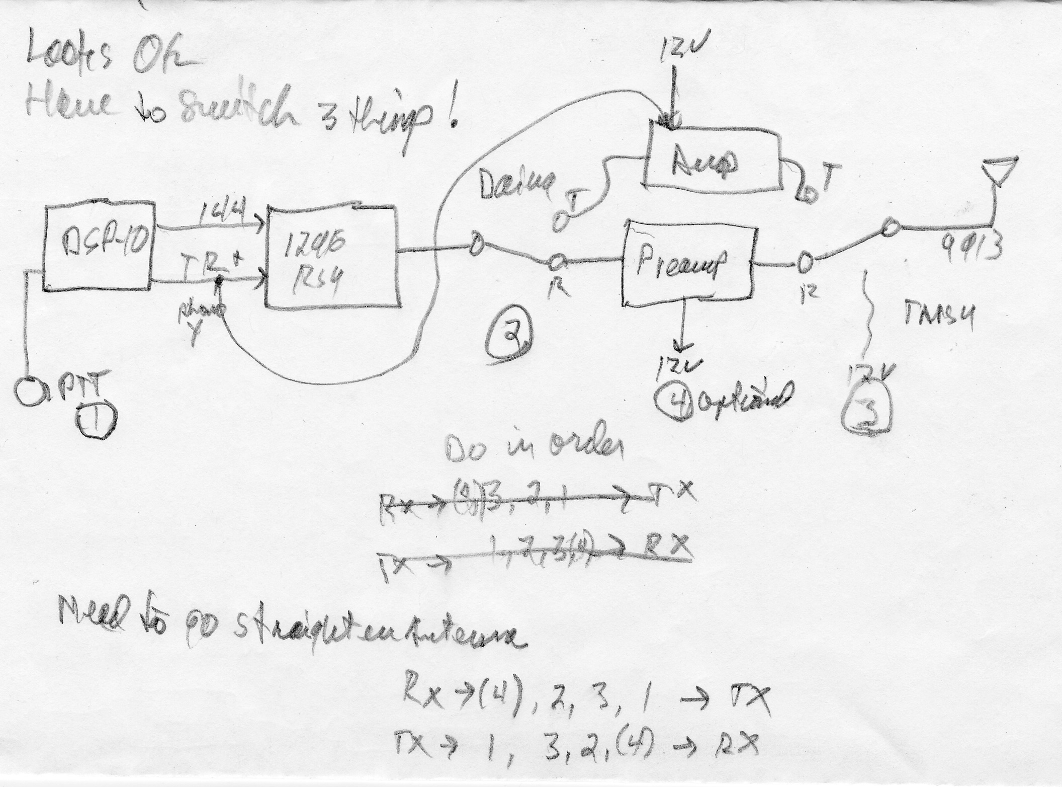
Returned to the switching architecture problem by making a list of all
the switching outputs available from the DSP-10 and all of the
switching required by the RSU. Made a list of things to do.
1. Discuss sequencing with W7PUA.
2. PTT out to 2330, part of the rebox.
3. Will need a 30 to 300 mW amplifier. Ask W1GHZ.
4. Will need an LO filter to knock it down another 30 dB.
5. Do the Brickette this way too. (Make more work for
yourself!)
6. Mods to 875 (2 meter linear) that match this. Add a
switch to select RF sensed T/R versus DSP-10 driven T/R versus no
TX. (No, this is not a 23 cm issue.)
Note on LO filter. At these wavelengths, signals are very
directional and narrowband beams provide some LO rejection. The
regulations are not specific, but one wants to be a good neighbor by
getting undesired products well below 0 dBm or 60 dB below carrier
whichever is higher.
Oh...
2.5 Patch and maintain antenna.
2010 September 11 - First
Non-Fabricated QSO on 1296.
Ralph, K6TSK, DM03, Net Control did not know where I was and was not
pointed at me, yet with many repeats he got my information and invited
me to check into the net every Friday. The "three switch TR"
configuration made this quite difficult. No receive without all
three switches thrown and he would often be in the middle of his
transmission by that time. Or would nearly give up when I was
switching the other way. He was 529. I did not get a
report, but 'many repeats' is an indication of poor signal.
9/11/2010 03:33:00 K6TSK 1296.09912 CW 2.5 W 529 / many
repeats. DM03 Ralph.
2010 September 17 Posted
questions about the 2300PAK power input and output levels to the
4-States Microwave list and Paul, W1GHZ. Paul suggeted a VNA-25 for the
intermediate gain amplifier. (Looks like it doesn't go to high
enough power.) No other responses.
2010 September 24 - Patch and Maintain Antenna
Took down the antenna, painted and tried to straighten it
by compressing in a vice. Dried. Tested indoors.
Tested outdoors. Finished paint in situ.

Studied the W1GHZ filter articles in QEX (2010 Jan/Feb);.
Found just the amplifier needed at an online outlet in Autralia.
Says it is designed to drive the RA18H1213G part. Minikits EME
162-1200 Ordered one.
Knowing now what the amplifier would be, drew some more architecture
pictures and decided I needed a better tool than a pencil for this.
Also made another long term Barely Works Technology list which I won't
reproduce here because it is already obsolete.
2010 October 26 - Relist the Rebox
Always thinking I was only a few hours from completion, made the
following list of things to do, then numbered the list in "likely"
order when done.
10
Tear down temporary 23 cm
20 Put 2 m. back on
30 Collect 23 cm boxes, draw picture, size chassis
40 Figure out all internal and external cables, connector,
8-pin, RF, etc.
Have real analog meters (current, field
strength)
Have an on/off switch for transmit functions
Leave room for 2 filters
1280-1300
1260-1280 for satellite / repeaters
velcro them in for manual change
50 Order chassis, cables, switch, meters - need low loss
cables
60 Read about interdigital filters
70 Order HW (11/22, 11/23)
44 Decide about power: power pole through grommit or
power pole to power pole
80 Draw control board on paper, check
90 Go to PCB
Express Batch PCB, transfer to there (11/22)
186 Check control board for 432 design
82 Make parts list
100 Order 3 PCBs
110 Order 5 sets of parts
42 Figure out internal boxes, connectors, feedthrough caps
120 Put LO in box
130 Put RSU in box
140 Build PCB
150 Wire up stuff
160 Drill up chassis - mount stuff
170 Final cable, testing
180 Put back on DSP-10
200 QSOs
115 Do comprehensive IM spreadsheet and levels
for 23 cm
for 70 cm design
for DSP-10
189 Check NF on RSU 1st receive amp
112 Order chassis punches
118 Sketch out 432 design as a check
145 Build interdigital filters
146 Tune filters, measure S-parameters
190 Characterize NF and PO
49 Scrounge parts
112 Build 1W PA from Australia
25 Check if 2330 fan blows up or down
34 Find switch and analog meter for power meter, size them
36 Power distribution approach
132 Build Minikits amp -> RSU box
172 External box labels
152 Tune up 1W, measure stuff
Also made up an OSH shopping list, mostly for mounting hardware,
but including a 6-32 tap for the filter construction. (Check
dad's stuff first.)
Started into the dissassembly that would cause me to be off of 23 cm
until most of the rebox was finished.
Found the lid on the old, small RSU/LO box was upside down and
insulated by its gasket. Apparently the thing hadn't worked with
the lid in contact.
Returned the system to 2 meter and was appalled by the local noise
levels.
2010 November 5 - Shopped for Boxes
Disassembled the old RSU/LO box, sized things up, and shopped for boxes
for these components, and a larger box that would hold all of the
boxes. This took a lot of time in part because I was thinking
things needed to be small and tight. That is a mistake for a
homebrewer. Need 100% margin on everything, counting wavelengths
in boxes. For the big box, settled on a Hammond
518-0920.
Added cable adapters and mounting kits to the shopping list.
2010 November 11
Read the EME 162-1200 assembly directions and made some
mounting decisions. Ordered the boxes from Mouser.
2010 November 16 - Meters
Looked around for an old, ugly meter I could use on the front
panel. Only found a 3A, not big enough. Thought I had a
field strengh meter somewhere, from my Novice days (when I used it to
incorrectly peak my 40 meter transmitter up on 20 meters and got an OO
notice!)! But, couldn't find it in any of the junque boxes.
Maybe in the attic? Took a cursory look in the attic -- probably
not. Very tedious making the long, detailed list of every cable,
length, connector, adapter, that will be needed. And there's a
few things on there from OSH too.
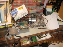
This is the power distribution diagram, kept correct with an eraser
through to the final product. The circled "36" means that this
was item 36 on the above list.
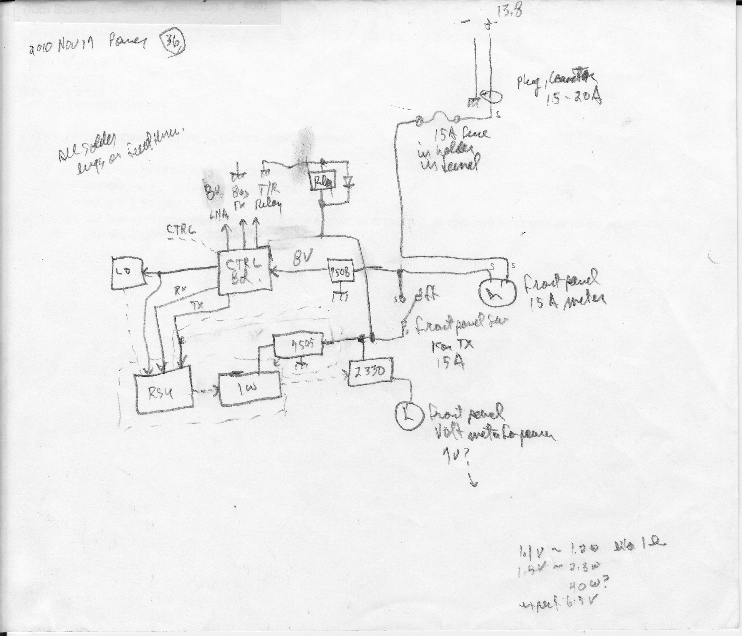
And this is the RF cabling plan. Both the desired lenght and the
"can buy" length are shown, but neither would turn out to be correct.

2010 November 19 - Finished up the
Parts and Cable Lists and Placed the Orders
2010 November 20 - How does one produce PC boards without having
chemicals in the house?
Started with two requirements: Mac and affordable. Research:
PCBexpress.com
- Used by W1GHZ
- Free Software
- Fast
- Windows only
4pcb.com
- Used at work
- Windows only
- high end
batchPCB.com
- Need a login
- ready to take orders
- batch every 2-3 weeks
- uses:
CadSoftusa.com
- Mac (!)
- Tutorial
- Reviewed in Spectrum, 2010 April, p. 24 -
25.
Downloaded CadSoft as freeware.
2010 November 22
- Design My Own PC Board for
the Very First
Time
Went up the CadSoft learning curve as quickly as I could. Learned
some lessons. After a carefully thought out hand drawing, I got
into the tool and started producing a schematic. Had all the
beginner mistakes with the schematic and, later, with transferring it
to an actual board layout. Had to pick parts out of libraries
then try to order ones that actually matched those footprints, not that
it would be super critical in this application.
All I needed for this project was this:
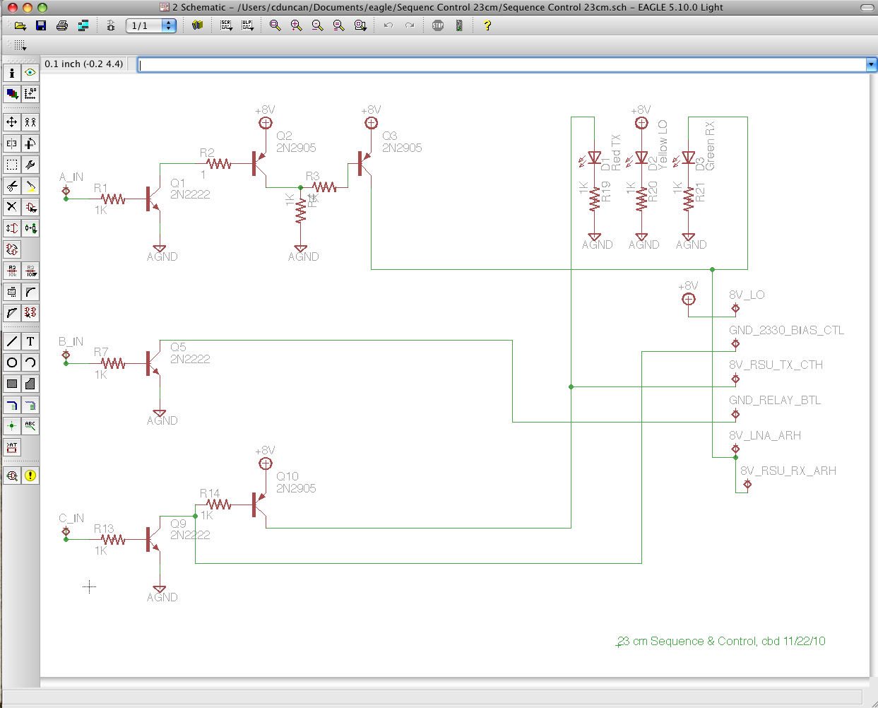
But since I was going to have three made and I might be able to use
them generically for other such projects, I ended up with this.
Which layed out as:
Then I could just populate the parts I needed to use.
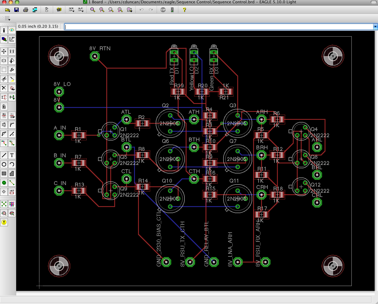
The basic idea was that this would take three control inputs:
A first in sequence
B second in sequence
C third in sequence
and whether they were active high or active low, would translate them
into active high or active low outputs, any of the four states being
possible. These generic controls run from left to right. On
the bottom are the specific outputs needed for this project:
Ground B to activate a transmit relay, High A to power receive
circuits, and so forth. As with the proto-control board before
it, there are three LEDs
Green - RX circuit powered
Yellow - LO powered (i.e., "on")
Red - TX circuit powered
The board could then be mounted so that these LEDs would give an
operating
status indication to the outside.
There are some oversights in the circuit, as will be discovered later
but for a first time out in one high-stakes 11 hour day, it's not bad.
Learned all about Gerber RS-274X and Excellon Drill files.
PCBexpress would also take the job files from this program, so I went
to them for a quote. The constant property of the quote was that
I was going to spend about $360 no matter how many boards I
bought. That is:
1 @ $360 or
2 @ $180 or
3 @ $120 or
5 @ $ 72
When you got into the hundreds you could get them for about $65 a
piece, but I just wanted one at that price. This pricing would be
OK for a club project on a proven design, but I was not willing to go
that steep on my first outing.
So I went and signed up with batchPCB and after fooling with getting
the files just right, got a design approved and placed an order for
three units that went into "Panel #1154" which was currently 69%
full. When the panels are done, they go to China for processing,
then are cut up and mailed to the individual designers when
finished. By the next day they were on panel #1158 so it looked
like I might be getting quick service. Not that it mattered...
Because then, I went off for the holidays, not to return to the project
until next year, well after the batchPCB order arrived. (And when
it did arrive, it had six copies of the board in it, for some reason.)
Biggest mistake: How did I manage to forget to put my callsign
and date on the board
artwork! Always something.
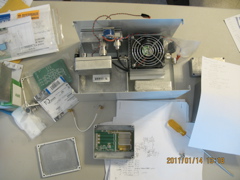
2010 December 22 - Clean work bench and try to proceed.
Check in orders, fill up the 4-40 and 6-32 spacer hardware
boxes. Organize everything. Read up on interdigital filters
in QEX 1999 Jan/Feb p. 3, 2009 Nov/Dec p. 40, 2010 Jan/Feb p. 20, and
2010 Mar/Apr p. 23 as recommended by author W1GHZ. Begin to
realize that anything at shorter wavelength than 23 cm is getting more
into precision machining than electronics. All the waveguide
sections are interesting but not directly relevant. Note that
WGFIL is by my former JPL colleague Dennis Sweeny, WA4LPR.
Note: 1152 / 1296 is 0.89 (precisely 8/9) which helps in reading
the normalized plots. (That's because 1296 is 144*9.)
Checked in parts from prior orders. Did more shopping research.
Had planned to spend at least 20 hours on the project over the
holidays. These four hours were it.

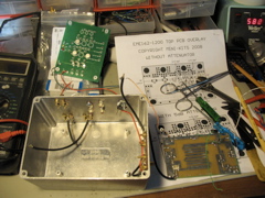
2011 January 14 - Assemble LO
Cleaned up the work bench again, fix mom's battery checker, look
through my planning papers and figure out what I'm supposed to do next.
Drill holes in proposed LO box and mount it. Add ground lugs to
the shopping list. Made an extra hole for power into the
box. :-(
2011
January 15 - LO, RSU, and 1 W.
amp Assembly
Tested the LO output with the ABPM. Not enough output to read on
the counter. Estimate -15 dBm with the lid off, -20 dBm with it
on. Make note that I may have to attempt operation with the lid
off. This is irksome because I'm putting the thing in a box in
the first place to provide some isolation and reduce intermodulation
products. Lesson learned - need bigger box or just determine that
individual boxes are not needed.
Begin assembly of the EME 162-1200 linear amplifier bought from VK5EME
in Australia. The nice thing about ordering from VK is that when
you need support late at night via e-mail, it is during their
workday. The board is designed to drive the Mitsubishi RA18H1213G
(the module used by the DEMi 2330) to full output from transverter
levels. I built it without the included 5 dB input attenuator so
that I could control the input levels from DSP-10 driver over full
range. (This may need to be corrected later.) It is
supposed to compress at +29 dBm (800 mW) but I want to operate it in
its linear range and only need 200-300 mW (+23 to +25 dBm) to drive the
2330 into its own saturation.
The EME 162-1200 is based on the Avago ATF-50189
Enhancement Mode Pseudomorphic HEMT (SOT 89 package) with nominal 17.5
dB gain. I planned to bolt it to the side of the RSU box for heat
sinking purposes. Inside the RSU box, I did not use connectors,
just soldered RG-174 pigtails. SMAs go to all the outside RF
signals.
Construction was fiarly straight forward. At 2330 local, I
estimated 20-25 hours remaining on the entire rebox effort. As of
the audit performed 2011 July 5 (when this story is being compiled) the
actual completion time, not counting the final tweak list, was seen to
be 98.2 hours!

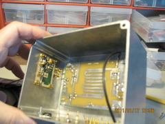
2011 January 17 -
Drill and mount all
parts in the RSU box
This includes all SMA connectors (my drill patterns look like Charley
Brown's Haloween Costume), all DC feedthrough capacitors, the
1296RSU
board, and the EME 162-1200 board with heat sinking compound.
Learned to just drill all but one of the holes on any pattern too big
so as to get screws in them at all.
2011 February 14 - Assemble the
home-designed switching board
No assembly problems. Will want to tie
inputs A and B (preamp off and relay on) together because the DSP-10
currently only supports two
sequenced output signals.
2011 February 21 - Drill holes in the
Hammond 518-0920 ("big box")
Made RSU and LO box labels. Start into the holes in
the big box. This will include square punched holes for the power
input and the two meters, mounting and through holes fo the relay, and
mounting holes for the switch and all the internal boxes.

2011 February 25 - Continue drilling
Struggled with the making of holes that the existing boxes with their
mounting hardware would actually mount to. Slotted some
holes. Drilled a new set in one case when the box overlapped its
internal 3-D footprint. Made some ugly extra holes even for the
LED displays on the front. Plan (without much hope) to cover up
some of this with the paper labels taped on later. After all this
struggle, essentially finished all the holes on all the boxes.
2011 March 4 - Yet another attempt to
"finish"
Wired up the RSU box inside, including the EME 162-1200. When
ready for the 162 bias adjustment, jury rigged a hookup. Came up
at 387 mA. Adjusted for the specified 280 mA. This will
need more tuneup. Struggled for now with the soldered coax
connections.
Had to move the mounting screws in the LO box and discovered, once it
was done, that the crystal on the bottom of the LO board interfered
with one of them. Had to move the board mounts too! In this
process something popped on the board. Inspection and search
found nothing. Any problem will show up later, I'm sure. (See March 25.)
Removed the sleeve on the 2330 input connector as it won't fit in the
big box. Looking into that connector, the pin pattern is
2
4 1
3
And the connections are
1 Red
#22 13.8 VDC input (10 A.)
2
White
Key (ground for PTT to activate bias)
3 Blue #22 & Black Ground
4
Green
Relative power from output diode to 10V panel meter.
2011 March 25 - Try to remember how to
proceed
Clean up work bench and look at task list from October to see
how to proceed. Wire up DC harness from control board. Do
DC voltage checks; all OK.
Make up 8-conductor DSP-10 to 23cmBox cable. Test cable and test
for signals when plugged in. Note that the DSP-10 connector is
wired backward so the 23cmBox input is also wired backward. The
cable is just one-to-one and doesn't care.
Cable Doc:
Ctrl
Board 23cmBox Wire Premade Cable
DSP-10 DSP-10
Signal
Connector Color Wire Color
Connector Signal
1
Red
3 E1 (not used)
A, B
2 Gray
Yellow
2 Ant Relay, 5.02 V TX
C
3 Brown
Blue
1 Power Amp, 5.02 V TX
delayed
4
Orange
5 E3 (not used)
5
Green
4 E2 (not used)
6
Brown
7 NC
7 Blue
Gray
6 Gnd
8
Purple
8 5.02 V
Gnd
Shell
Gnd Chassis
Signals on my interface board:
A RX and preamp power
B Relay
C TX power and Amp enable
D Apply drive (handled internally by DSP-10)
Looking into 23cmBox connector from the outside it looks like
slot
6 7
1 8 3 ^ up
4 5
2
But there was a problem. Neither the control board nor the 7808
nor the 1296RSU were prepared to handle the 1+ Amp needed by the EME
162-1200 to be regulated down to 5 V. On transmit, the 8V TX line
sagged to 5.88V.
The solution was to take out the RSU box, drill a new hole for a new DC
feedthrough and connect the EME 162-1200 7805 regulator to the front
panel switched transmit DC. This means that when the front panel
switch is off, the 1296RSU will transmit 50 mW into an unpowered
stage (instead of the 162 transmitting one watt into an unpowered
amplifier stage). After this change was accomplished the unloaded
(key up)
transmitter voltages were
RX TX
Vin 13.99 13.98
8V TX 0.06 7.56
8V RX 7.63 0.00
8V LO 7.71 7.69
Switch off on
Vin 0.00 13.93
5V EME162 0.00 5.00
Then turned to the VK5EME 162-2000. Found the bias at 266
mA an readusted 500R for spec. 281.1 mA. This was good, but there
was no output for input drive up to DSP-10 drive setting 100.
Took the board out and tried it. Still nothing except when it is
mistuned into self oscillation. This is wrong.
Disassembled the LO. The 64 MHz was OK, 10 dBm. The 192 MHz
was OK, -5 dBm. The 1152 was not counting at all. No power
indication at all.
So, remember a few weeks ago (March
4) when we were working on the LO box and
heard something pop and couldn't figure out what had happened but
figured that we eventually would figure out what had happened?
Well, on close inspection, it was found that the MAR-6 number A3 was
missing.
Missing.

Right there under the power input on the upper left, no MAR-6 in
position A3.
Tried ordering some and found how difficult it was. Finally found
a guy with some for sale out of his junk box. Scott's Electronics.
Then, as I usually do in such times of crises, revised the todo list.
2011 March 26 - Trying to Proceed
But wait, didn't I originally buy two
1152 LO kits, thinking to hack
one into a 576 MHz LO at some point? And wouldn't that kit have a
couple of MAR-6 in it? Yes!
Stole the part out of that kit and installed it. Bias on A3 was
3.37, correct for 8V supply. ABPM estimates -17 dBm out of the
box with the lid closed (312 mV) and the counter says 1152.008 MHz.
Hooked up the oscilloscope and measured the key up delays on the two
lines.
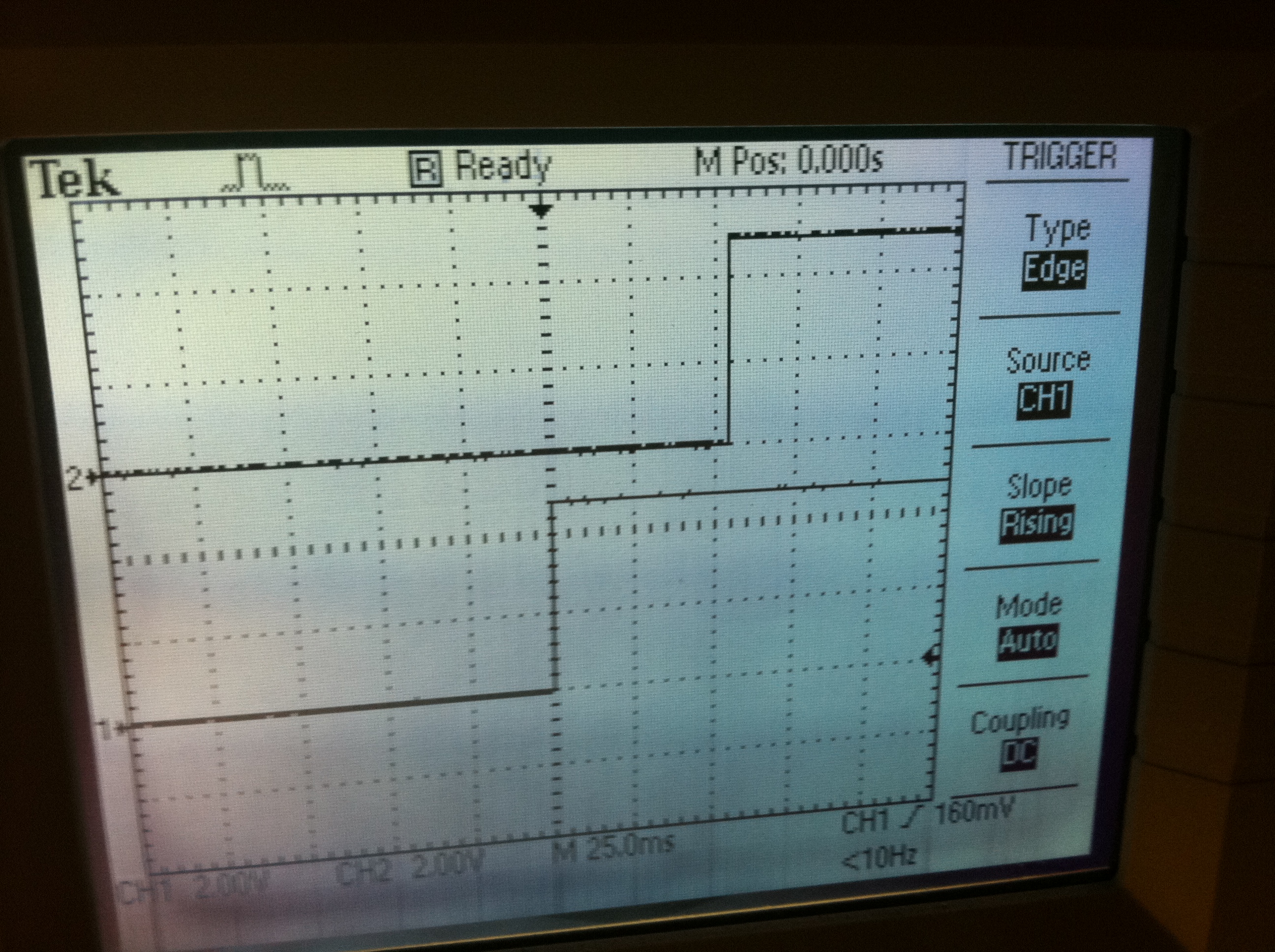
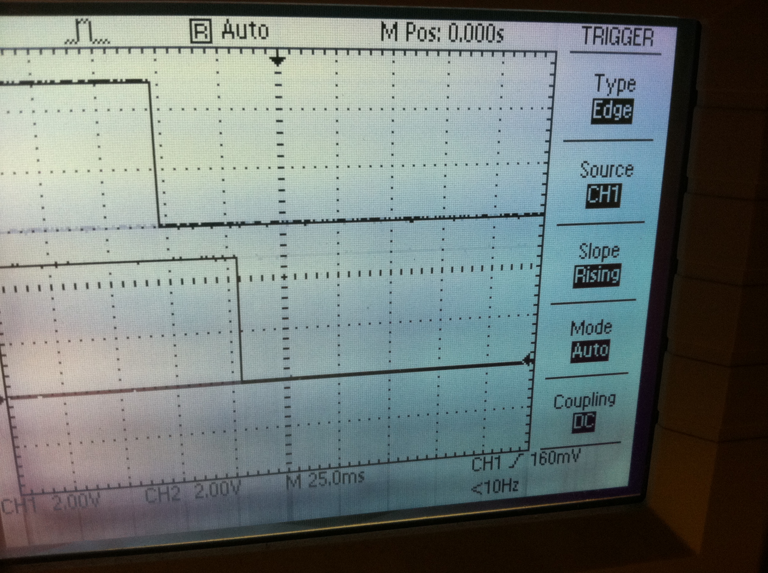
That's about 50 msec between preamp off (A) / relay close (B) and
transmit power (C) on switch to transmit (left)
and about 30 msec between C and A/B on switch to receive (right).
Ch 1. (bottom) is the gray wire (A/B), Ch. 2 (top) is the brown wire
(C).
That does what is needed. I don't recall if I have control over
this in UHFA.CFG but it doesn't matter.
Now use the ABPM to measure power levels.
DSP-10 @ drive 100 measures +13 dBm - nominal
Put that drive into the RSU and it measures ~ +4 dBm which is
low. ABPM is not a precision instrument, but this is still low.
Counter measures 1296.109. That's reassuring for now (not setting
frequency yet).
Put lids on boxes and mount them.
LO box lid and mounting have no effect on power output (even though
they affect LO power output).
Putting RSU box lid on drops it about 2 dB to +2 dBm (again, the ABPM
is not a precision instrument).
Drive the DEMi 2330 with this and expect +25 dBm output.
Bird 2.5K reads 0.57 W which is +27.5 dBm. That's good and
reinforces the idea that the ABPM reads a little low.
(Note: The ABPM was "calibrated" for this by putting 144 MHz of
"known" (KA7EXM meter measured) power levels into the VHF and UHF
inputs. ABPM is likely to read lower at 1296 MHz for which there
was no calibration source.)
Reinstall the EME 162-1200
Check the bias. Find 276 mA, tweak to 280 mA.
Check regulator: 13.92V in, 4.99V out. Good.
For +4 dBm in, predict +21 dBm out (1/8 watt). It was at 27 dBm
out when the 8V regulator burned up, fiery hot. This was due to a
short in the 8V in the box, not the transmitter testing. But the
part had not been heat sinked because the sink would interfere with
mounts and it was not supposed to be needed at a fraction of an amp.
After dinner, cannabilized the chassis mount 7808 out of the old RSU
box, drilled a new hole on the new box, and mounted it to the chassis.
Check: 13.69V in, 7.95V out. OK.
Hint: If all the lights on the control board go off, there is
probably a short on or near the 8V LO line.
Resume tuning on EME 162-1200. Very sensitive to tool
removal. Tuned for +25 dBm with tool off - should be plenty to
drive the 2330.
Took some preliminary linearity data. In the process, exceeded
2.5 W on 1296 and has to swap to the Bird 50K for the very first time!
The data indicated compression around 42 dBm at DSP-10 drive level 72
(-10 dBm) and saturation at 44 dBm (24 W.) This seemed OK.
Feeling ready (yet again) to "finish up", installed a 1N4148 diode
across the Tohtsu
CX520D relay and mounted it on the box.
Doing a basic continuity check on the hookup, got a smart RF burn off
of the common relay terminal. That indicated that it was hooked
up correctly. I would not realize until later that the transmit
system was
oscillating. One carefully measured and ordered SMA cable
wouldn't reach. Had to
rethink. Hammond box, large as it is, is too small. Tetris
is diffult when the pieces are connected by cables with bend radii at
various points.
On the first key up into the dummy load, got 30 W out before drive was
applied - oscillation.
Took things apart and rearranged cabling. The 2330 to relay
cable, for example, wrapped around the preamp. That can't be
good. Took the lid off the RSU box and could get misbehavior and
different behavior by moving my hand around inside it. Broke the
white enable wire off the 2330 while doing this and wasted time trying
to discover this to figure out why it wasn't working. Replaced
the wire with a
black one that was more robust and better routed. Everything is
so packed that it is difficult and time consuming work. Left the
box working at the end of the day but it would break into oscillation
when I would sit at it to talk, didn't seem to perform like it should,
and was several KHz off frequency (wen it did work). Leave it set
at:
DSP-10 80 (-2 dBm)
Output 11.0 W (40.5 dBm)
Field Meter 3.6V
Input Current 6.5A
Lots left to do and documentation is a mess, but at least I can monitor
again, and it's on the air after a fashion.
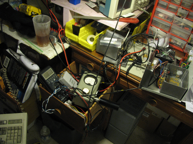 ;
;
2011 March 27
Able to monitor but don't know what frequency I'm
on. Played around with Argo, 10 MHz, Metex counter, and WWV.
Also found a problem in the control board. When unpowered, the
2330 pulls down the enable line enough to display a dim red light.
2011 March 28
Figure out what frequency we're on using a spreadsheet like this, the
first of many iterations:
DSP-10 frequencies,
3/28/2011
DSP-10 and 1296 RSU have been on
> 3 days
Freq. MHz Remark MXG-9802A on for
half hour, moved 0.5 Hz
10.000000 WWV
TS-680 9.999.50
493.400000
0.000017 DSP-10 TCXO delta measured by
Argo
510.500000
10.000017 DSP-10 TCXO
This is stable,
1.000002 DSP-10 TCXO correction
factor
modulo
144.200000 Desired DSP-10 operating
frequency
680 drift
144.199753 Tune DSP-10
10.000046 MXG-9802A measures DSP-10 TCXO, Ch.
A, checked Ch. B, agrees (less precise)
0.999997 MXG-9802A correction
factor
1152.000000 presumed LO
1296.100000 Displayed on DSP-10, CW for
carrier
1296.108545 MXG-9802A measures DSP-10 with RSU
(RF)
144.100000 presumed IF
144.100246 actual IF
1296.104819 actual RF frequency
measured
1152.004572 actual LO frequency
64.000254
1152.004819
LO to enter in UHFA.CFG to correct for both IF and LO
1296.100000 check: display
144.095181 check: presumed
IF
144.095428 check: actual
IF
1152.004819 check: presumed
LO
1152.004572 check: actual LO
1296.100000 check: presumed
RF
1296.100000 check: actual RF
0.000000 check: actual minus
displayed
1296.103890 check: measured
RF
1296.100164
check: measured actual RF
1296.100000 IC-T81A displays FM
1296.103020 MXG-9802A measures
IC-T81A
1296.099294
Actual IC-T81A RF
(shot batteries)
In each iteration the presumed IF is the IF currrently entered
in UHFA.CFG. A new IF is calculated from the measurments.
Once that IF is entered into UHFA.CFG, the display should be
"correct." The same series of measurements are taken to confirm
or
refine this. When the refinements got down to the 100 Hz level, I
stopped.
The last iteration indicated that the LO was at 1152.003056 MHz meaning
that the crystal was at 64.000160 MHz.
Made up some questions for next week's San Bernardino Microwave Society
meeting. Answers given here for convenience are from the group at
the April 7 meeting.
Q. DEMi says their 2330 puts out 30-35 W while the spec. sheet
for the part says 18 W minimum?
A. Have you ever heard of "marketing"?
A. If you're getting 25 W, just take it or you'll burn the part
up.
Q. DEMi says 50-75 mW drive for "full" output. I'm getting
12.5-15.0
A. Ditto about marketing.
Q. The EME 162-1200 says 800 mW out. The spec. sheet for
the part says 300 mW max. The kit does include an optional 5 dB
input pad.
A. Marketing.
Q. I had similar experience with the Brickette. The
construction article said 8-9 W but the spec. sheet said 7 minimum and
I got 7.2. Buying a new 10C slug, cranking up to 14.0 V, rewiring
the tuning circuit and minimizing DC losses, none of this helped
much. Do people just get hot parts, or have liberal meters?
A. Not asked or answered at the meeting but the lesson learned is
that it's in spec.
More on the 1.3 GHz amplifier: Mitsubishi RA18H1213G. It is
meant for FM service but will operate linear at reduced power.
This all agrees with what I'm seeing. Looks like I could run
FM/CW at 25 W., and could run 15 watts PEP linear. Plan to adjust
drive
accordingly.
2011 March 29 Stumbled Upon the
Current Beacon
Tailending his QSO with W6PQL up the coast, worked K6TSK / DM03, my
first QSO in the new configuration.
After months of sporadic listening at 1296.325 and 1296.329 where I had
heard a beacon some years ago I had heard nothing.
Looking for suitable beacons online I was listening for
http://www.ham-radio.com/sbms/beacons/Pt.%20Loma/ptlomabcn.html
on 1296.3 plus or minus .002 MHz.
The radio sat on 1296.300 for a while, 1296.302 for a while and
1296.298 for a while then I forgot about it for most of an hour and
went to paying bills while listening to noise out of the rig, a common
activity in my little man-cave
here.
Suddenly at about 10 p.m. I was jolted out of a reverie by CW!
After several tries (RST 219) I copied K6QPV/B with enough certainty to
start googling around.
The frequency, by my measure, was 1296.298 and I can see it
continuously in the waterfall but only rarely did it come up to "by
ear" copyability. This was exactly the sort of thing I had been
looking for to baseline the rig so I could know how the future
improvements (or degradations) were going.
After 30-45 minutes looking, I couldn't find anything about a 1296
K6QPV beacon, although there were many redundant mentions of beacons he
operates on 10 and 24 GHz and another on Light. These were all on
(in?) San Miguel. Seemed like mere 1.3 GHz was pretty pedestrian
But then, in a clever accident, I found
http://www.ham-radio.com/sbms/newsletters/2011nwsltrs/03sbms2011.pdf
where on page 6 there is an article by Greg Bailey, K6QVP himself,
mentioning in passing, nearly like it was hardly worth noting, that
N6XQ (from the above link) had QSY'd to South America and left his
1296, 432, and 222 beacons here where the local crew had put them up on
San Miguel, including one specifically mentioned as 1296.3.
Presumably this was DM12mq.
Searching for K6QPV and 1296.3 had found it.
The grid
square locator says that San Miguel is 209 km from here in
approximately the direction that my Handbook 8 element beam
points. Best 23 cm DX for me! It is a few miles south of
K6QPV's QTH in La Mesa and looks like about 20 miles southeast inland
from Chula Vista. Signal level varies from -148 dBm (or less),
just above my noise floor at 2.3 Hz (or below) up to -123 dBm or S-5.
2011 April 1 Checked into the Friday evening net on USB for the first
time.
2011 April 2 K6QPV/B
Corresponded with Greg about the status of the beacon and he said that
he intended to keep it on indefinitely, give or take maintenance.
Think about later architectural choices. Use a VCO/PLL? Use
a stabilized crystal and just count things against GPS or WWV for
knowledge. No "decisions." Will continue to run a "computer
ctystal" at 55C for now.
Need a better long term monitoring mode in SW, maybe with alarms for
band openings.
2011 April 7 Attended the San
Bernardino Microwave Society meeting.
See outline report, Q & A in March 27 above.
An important difference between my monitoring of the beacon and most
people's is that I'm looking at it in a slow FFT waterfall day after
day and can see, in addition to the amplitude variations that most
would see when they tuned by to see if the beacon was OK, also the
frequency variations that seem to go with conditions somewhere, and
spurs and other spectral features (that might be made at the
transmitter or at the receiver). Between both ends, I seem to be
having 1e-7 frequency stability on a diurnal cycle.
2011 April 8 More Cleanup
Reconfigured to try to tune up the EME162-1200 again. Found loose
cable that may have been involved in the feedback problem. After
tuning found that the output dropped by 5 dB or more when I put the lid
on. Made a lid out of cardboard from junk mail (cleanliness, not
RF containing). Took some amplifier performance data that is
suspect. Still have free oscillation when I key up to talk.
After checking into the net, made an adjustment to the EME 162-1200 and
made it better. Painted the tuning capacitors with fingernail
polish and it started oscillating again.... Wouldn't work right
with the big box lid on
either. That turned out to be because the big
lid forced two cables too close together, providing an unwanted
feedback path. Another several hours of debugging. Tried
putting ferrites on power lines - no difference. Decided not to
work on the amplifier chain anymore until the LO filter was built and
installed, as that will only change things again.
2011 April 11 Antenna
Went on the roof to inspect the 23 cm antenna. Still looks
OK.
2011 April 12 - Order W6PQL Crystal Oven Controller
Later may buy an oven that includes a 96 MHz crystal for the
1124 LO for the eventual 1268 satellite capability.
2011 April 23 - Build W6PQL Crystal Oven
Controller
Heard an airplane reflection on a CW signal during the net
checkin. Display not fast enough to catch it.
See http://www.w6pql.com/crystal_oven_controller.htm
. Assembled
the kit and made some measurements. LO box is now at 22C and runs
from 7.93 V whether TX keyed or not. Install and debug heater and
sensor. Came up to 66C! Seemed to settle at 71C.
Beacon not seen when receiver came back up. Listened
around. Did calculations. Challenging to find the weak
beacon at unknown frequency. Now at 78C.
Finally found beacon over 5 KHz away from previous. Rig came
unplugged, took five minutes to recover the frequency.

2011 April 26 - Set LO Frequency -
Easier Method (but requires Trust)
The LO frequency is not controlled, it is measured and the DSP-10
software configuration file is told the answer. It then takes
care of getting the display right. Assuming that the beacon was
on 1296.300000 and that I should have the 600 Hz CW marker on it (i.e.,
BFO should be displaying 1296.299400) calculated that the LO setting in
software should be 1151996456.0 Hz. Had previously made a chain
of calculations using Argo to reference the DSP-10 10 MHz oscillator to
WWV over the air, then calibrating the Metex MXG-9802A frequency
counter from that, then measuring a 1296.100 MHz transmission and
calculating in a spreadsheet what the LO should be. The present
calculation is much simpler and perhaps more precise. Diurnal
signature on the signal swings 800-1000 Hz per day with definite
sunrise, sunset, and apparent air conditioner activity. Some of
this seems to be on the transmitter side (DM12mq)and some is verifiably
on the
receiver side (right here). Room temperature and transmitter fan
activation
both appear to correlate to frequency changes but such changes also
occur when there is no local correlating temperature activity.
2011 April 29 - Change Temperature
On attempting to check into the Friday net, found the box
oscillating, putting out ~30 watts of off-frequeny noise. Opened
it up and replumbed the cabling and connectors to get rid of
this. Also, worried that I didn't want my LO board at 80C all the
time, opened it up and changed the controller resistors for a lower
temperature. Changed R3 from 5.1K to 10K and R7 from 1K to 3.3K,
attempting to get 50C, high enough to control, but not to cook.
Turned it on and it stabilized to 52C (All temperatures measured by the
thermocouple on the BK 390 Test Bench.) Struggled to get it
mechanically reassembled without power shorts. Struggled to get
it working without amplifier feedback. Remeasured the beacon and
changed the presumed LO in configuration to 1151994465.0 Hz.
Noticed after several days of monitoring that the beacon has a
consistent diurnal signature.
Unclear if this is on my end or beacon end, but appears to be
temperature related. Doesn't seem to correlate well with anything
going on in my shack.
But I can see my own the effect of my own cooling fan, here off
except from 2315 to 0044Z.
And sometimes I can see what appears to be a clear air
conditioner cycling signature, even when my own air conditioner is off.
Also, when it is really loud, I
can see and sometimes hear sidetones 15 dB down at plus and minus
400 Hz.

Sometimes military radar with a 12 second repeat pattern comes on to
make things interesting.
2011 May 20 - Replumb
Struggle some more with feedback. Changes in cable
routing and connectors seems to work (including one really annoying one
that was happening only when the main box lid was closed, pushing two
cables into proximity that weren't otherwise). Decide to build
and install LO filter before doing anything more. Some L
connectors are needed to make things fit and, at the same time, work.
2011 May 28 - Drill holes and assemble
W6PQL 3-pole LO filter
Drilled second hole in first box wrong. Went to
backup box. So much for doing the 1124 MHz LO for 1268 near
term. Everything on the second box went smoothly.
2011 May 30 - Install the LO filter and try
to close it out.
Close up LO filter.

In these views:
Top
Tune: A B C
Bottom SMA port:
1 2
Hooked up
23cmBox => filter => Bird 2.5K => MFJ dummy load
and found that A and C moved out about 4 mm to peak. B didn't
seem to have enough range so removed the locking nut and screwed it all
the way in then repeaked A and C.
Hooked up
23cmBox => Bird 2.5K => filter => MFJ dummy load
and tuned to minimize insertion loss. Final measurements at
1296.3:
S loss dB type
12 1.0 insertion forward
21 1.1 insertion reverse
11 16. return to source
22 16. return to load
pretty much as advertised by W6PQL. Forgot
to tune for 20 MHz bandwidth. Doesn't matter today.
Tightened and dobbed fingernail polish on the tuning screws.
Using the IC-T81A as a signal source with the Bird 2.5K 1.29 - 1.30 GHz
and the DEMi ABPM 1.24 - 1.29 GHz, made the following frequency plot.
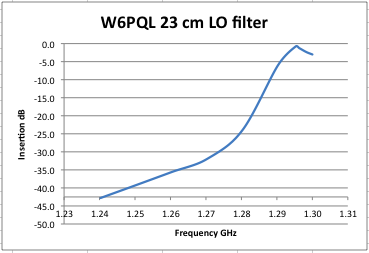
All measurements below 1.29 GHz are seriously coarse, but this does
confirm expected behavior and > 40 dB suppression at 1152 GHz.
Installed for measurements.
Shorted the DC power to ground with the filter. Replaced 20A
inline fuse.
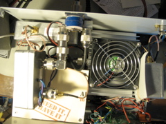
Even powered there was no RF output. Opened things up to
investigate. Worked acceptably with the RSU box lid off.
Went through the whole ritual of tuning for the lid, even taking
measurements with various screws in and out, tightened and not
tightened.
Finally installed the cardboard lid back in the RSU box, got it
working, and
took some performance data. The performance data showed
compression at DSP-10 62 input (the DSP-10 itself compresses at
98). Made a list of more things to do before plotting that data
and claiming done. But did put the outer lid on the Hammond box,
move the 23cmBox to its operational position, cleaned up the work area,
and declared it conditionally operational, pending a few last things.
2011 June 4
Found the beacon loud and set the waterfall to fastest possible
so I could watch the temperature control ring in on power up.
2011 June 11 - Participation in ARRL
VHF QSO Party
Per my mantra of contesting mainly to check things
out (see page 5 Op-Ed of Sep/Oct 2011
National Contest Journal), listened on 1296.1 USB and 223.5 FM for
the ARRL VHF QSO
Party. (For 223.5, see Utility Radio
PL Board in Midland 13-509 .) The strategy was to just work
whoever showed up on either one and it worked about as expected.
Made about half a dozen QSOs on each. Some on 1296 required
CW. Set the ladder next to the house so I could run up and turn
the 1296 beam as needed. Not sure that helped much. People
don't sit and call CQ for minutes and minutes while guys like me steer
around for them for them -- manually.
The new "rest" beam heading, 120 as opposed to 160 true, seems to bring
in the San Diego beacon (K6QPV/B DM12mq) at least 10 dB better than
before. Or maybe it's just propagation. There are good days
(nearly all copyable) and bad days (some not even seeable).
2011 June 14 - W6GL is working on
setting up his own 23 cm beacon in Thousand Oaks
Might be on 1296.330
2011 June 25 - FD
Attempted the same strategy for FD but the battery / inverter
configuration I use for class 1E didn't hold up the DSP-10 support
computer sufficiently. I could have rearranged things to fix that
but judged it wasn't worth the effort. Made 223.5 FM contacts
(about five) as people came along until the battery (running
computers and things too) sagged after four or five hours, then went
QRT. Listened to 1296.1 for the entire test period and only once
heard a brief QRZ. Perhaps I saw something in the waterfall one
other time, perhaps not. So it wouldn't have been worth it.
It was more important to make progress towards the next major task -
Mac SW for DSP-10 support, so that future contests can be supported
differently and by a non-110A/C computer. I don't intend to buy a
386 compatible laptop or fool with all that XP or Windows 7
compatibility stuff for this.
2011 June 28 - Truth In Bookkeeping (duh duh duhhhh)
Started a "truth in bookkeeping effort" as part of the 23cmBox
completion. The idea is that I started this effort in spring of
2009 thinking I'd spend about $90 and get on 23 cm after a fashion
based on the W1GHZ 1296 RSU design within two or three weeks. At
least I managed to contain
myself and not buy all the transverters in his four-band scheme, but
thought I'd see how it went with just this one first. Having
built it up and
having used it, I found it didn't do what I wanted, so I started adding
stuff. There was never a clean plan or a stated goal, but at this
point I have it working, nearly right, and am wondering what
happened. So, over the upcoming five-day weekend, I'm going over
all my notes and orders, totalling up the cost in time and dollars, and
putting the completion story here. The result from this review
will be the ability to estimate and select future projects better and
trade off properly between buy-build-purpose. One would hope.
2011 June 29 - A Beacon Reboot Seems
to Have Occurred About 0200Z
See it ringing in like it did when I restarted, but much
more slowly?
2011 July 3 - And it seems a lot more
stable diurnally too.
Don't know if that's related to the reboot, the
current weather, or anything in particular, but it does tend to confirm
that my LO is stable within 100s of Hz.
The +/- 400 Hz tones seem to be gone too.
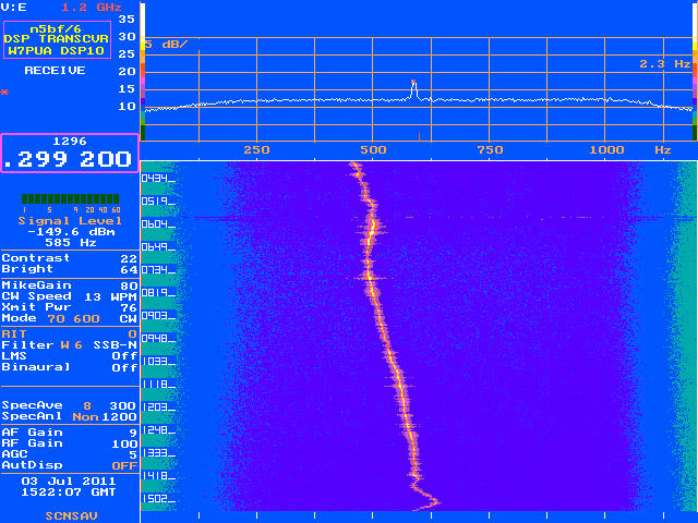
Based on this, I set the LO frequency in UHFA.CFG to 1511996056.0 Hz.
Note in these pictures where CW mode is indicated (Mode is half way
down the left side) the red mark at 600 Hz corresponds to the transmit
frequency meaning that the BFO frequency implied in this figure is
1296.298600. The Hz scale along the graph is relative to that.
2010 July 7 -
Truth in Bookkeeping
In the midst of all this it occurred to me that there might be
engineering and system engineering lessons to be learned from this
whole experience. I started out in March 2009 to get on 23 cm for
about $90 in two or three weeks of my spare time. Two and a half
years later, I have over 270 hours and over $1400 in the project.
That is roughly one year worth of BWT time and one year worth of BWT
money, a factor of ten or twelve more than expected.
So what happened here?
Well, the 1296RSU was designed to get rovers on the air on new bands
for contests. Mountaintopping with a beam, a coordination
frequency, and other stations not that far away you could probably work
a few on 50 mW with a front end at a few thousand Kelvin. But I
wasn't even able to check into the local net on that from my home
location. I made
improvements in the right order: antenna, front end, power out,
and by then there was so much new stuff that a new box was needed and
new circuits were needed to manage everything. This is more than
the typical "factor of pi and a unit of time" underestimate. This
was plain not
thinking about requirements in advance. Then, as things were
added, new problems were discovered, some of them the classic beginners
problems: box too small, striplines not workingt right in small
boxes, can't run cables too close to each other at these power levels
at this frequency, shorting things out, blowing fuses, burning out
parts, getting RF into sensitive places (including my finger!), the
list goes on and on.
And I can't drill a hole in the right place to save my life, even with
a drill press.
It has taken me about 25 hours, about 8% of the total time on the
project, just to collect this information from my notes, while telling
the story, which takes another 10% or so. Is the overhead worth
it? Well, when I started in I thought not. "What am I
doing? I could be writing the software now!" But, diving
into the work without thinking about what the work is -- again --
doesn't seem wise. I've learned so much from the trends and
patterns as well as the specifics that I think it was well worth the
effort. No one likes rework. I would rather tell stories,
or have the adventures from which the stories are made.
This has been five or six times the effort of getting the DSP-10 going
in the first place! But that is because it was always a less well
defined problem and I was further out on the frontier (the
wilderness some) for the first time. I feel ready to take the
next step. To design the entire thing myself from the ground up
(70 cm this time). That will take a long time too because there
are still lessons I haven't (re-)learned. And then, maybe I'll be
where I want to be, blithely cranking out hardware like I want, or I'll
have it out of my system and spend the rest of my effort on the
wonderful things that can be done on this platform with the software.
Lessons Learned
Mechanical
- Drill all but one of the mounting holes too big so you can get the
screws in all of them at once.
- Get a box twice as big as you think you need. (Yes, 100%
margin.) This is not the time for Tetris. Rethink station
placement and portability assumptions.
- Need bigger box for components that have hairpin filters too, at
least half wave apparently.
- Are individual boxes really needed? If they are, don't put a PA
in the same box with its exciter. That's where isolation would help.
- Put parts and wires in holes first.
Electrical
- Trust the spec. sheet on the part, not manufacturer marketing.
- At 23 cm everything is a cavity. Mechanical finesse is needed
to get things to work and not malfunction (i.e. oscillate).
- Regulate your LO voltage as well as possible in the presence of
variable TX/RX supply loads.
- LO temperature stability is nice.
- Careful with DC. I always burn up a few fuses and parts due to
DC shorts.
Operational
- If all the control board lights go off - disconnect power
immediately. (and check RigRunner fuses)
Administrative
- Tell the story as you go. It's not worth doing all 10% story
telling at the end.
- Spend three times as much time getting the concept and the design
right and earn a third of the time trying to get it to work without so
much rework.
- It is not useful to have a separate "Utility" category. Just
keep hours and dollars in the spreadsheet categories and monitor the
percentages for reasonable intent.
But, all that said, still, give me a call on 1296.1!
2011 September 24 Closing out
the 23 cm development - figuring out how well it works
Start working on the 23 cm closeout list:
- LO voltage versus configuration. Supply voltage into the LO is
7.92 regardless of transmit/receive, key down/up, switch
on/off. No change needed.
- Noise Figure measurements.
Using the noise source powering scheme where a circuit adds 13.6
battery voltage to an adjusted output from a MFJ 4035MV power supply to
get 20 V, checked the voltage frequently to avoid effects of supply
drift. By doing this kept the variations down to a few tenths of
a volt rather than several volts (up to 3-5) I had discovered on
previous measurements. Also accounted for temperature.
Today the room was in the 300-303 K range as opposed to 290 K that it
had been in previous measurements.
xxxx quit on 10/29/11 to finish later
Entered into an extensive analysis of system noise figure, trying to
match analysis to measurements that didn't end until 10/15/11.
That will include the analysis, the measurements, and the explanation
of better than measurements -- either source is hotter or measurement
is nonlinear, probably not at 20 dB difference. Might try some
(external only) with the Pasternak (@ 23 cm?) to see if that is
different.
But basically report the results on all the stages and what I had to do
in the analysis to get agreement, then give the "final" table and maybe
the dBm/bits table.
Then talk about the TX gain chain and analyze that with compression,
etc.
Power Charts.
Talk about drive settings.
Show pictures including absorber inside the RSU box that fixed it
shut. But to get power out of the LO, need the lid off.
The closeout to today including the summaries from the cost chart that
is currently up to September 24.
And the IMD chart showing the gains and mixing products of all the
mixers, filters, etc. to predict what I'm seeing.
And that's it. Maybe move the lessons learned down to the very
bottom.
n5bf/6
DSP-10
page
n5bf-at-amsat-dot-org
opened 2007 August 14, cbd
updated 2011 October 29, cbd
(c) 2007, 2009, 2010, 2011 Courtney B. Duncan