DSP-10 Software Radio
Test Equipment Page
back ton5bf/6
DSP-10 page
From the outset of my career in amateur radio, it was clear that I put
value on developing and building in addition to operating. A few of us are
like that. (One of my early "locals" W5JRM is one of those too.)
I can remember in the early 1970s talking with WB5FID's Elmer W5LHX and my own
Elmer W5KRZ saying things like "I want to build a synthesizer." A fairly
universal response was, "Son," (in Texas, every male calls every younger male
"son") "Son, you need to build up a collection of test equipment."
So here we are. Test Equipment.
W7PUA says in his DSP-10 articles that you can debug many things with a good
multimeter, and he's basically right. But, sometimes there are things you want
to measure beyond just getting something working. And, sometimes debugging can
be faster (for those of us who have less than brilliant moments anyway) with
additional gear.
The History of Test Equipment to
Date
All that advice notwithstanding, I didn't really catch on to this until
recently. Looking around the shack, what test equipment do I already have that
is grandfathered in to this story? I have a borrowed Heathkit Reflected Power
and S. W. R. Bridge, Model AM-2 (HF) that I've used nearly from the
beginning. (It was still borrowed when my Elmer W5KRZ passed away. I still
have it and have used it to load up many, many antennas HF through 2 meters.)
These days I use an MFJ-202B noise bridge to tune my Rockmite to random wires
with a 30 year old MFJ-16010 long wire tuner.
The first piece of test equipment I can remember buying and building was the
classic Heathkit Vacuum Tube Voltmeter (VTVM) Model IM-18. You can see it
sitting there in some of my shack pictures, but I haven't actually turned it on
and used it in many years. It was a marvelous device in its day but now, in
the era of high impedance FETs, is an antique. I have never forgotten the
calibration step, "A brand new D cell is usually about 1.62 volts...."
In the garage, I still have a Heathkit RLC Bridge Model 18-528 that 1 that I
built from a kit in an ancient attempt to stock up test equipment. It worked
when I built it but I haven't used it in years.
One thing I still do use all the time is a Heathkit HN-31 50 ohm KW dummy
load. It sits in the shack waiting to be hooked up to any radio any time.
When I bought it in about 1979 I remember getting transformer oil to fill it
with. Yes, you could still buy transformer oil at Heathkit back then. Rob,
WB5FID talked me out of using it though and I returned it, filling the dummy
load with mineral oil instead. I've changed it once in the intervening 30
years. According to the graphs on the side, the RF performance is a little
worse at high power, but I've rarely used it at high power and when I did it
did just fine.
My "good multimeter" these days is a ten year old BK Test Bench 390 (black, not
like the new blue ones). In addition to the usual things (volts, amps, ohms,
DC, AC) it also has a continuity beep position (for buzzing things out) a diode
checker, and, most impressive, frequency, capacitance, and temperature measurements (F and C).
Yes, it comes with a thermocouple. I got it to replace my 388A BK Test Bench
(yellow, not like the new blue ones) when its display quit, but then had the
older one fixed so I now have a way to measure voltageand current at the same time. There's also
an AC coupler pickup with which you can measure the current your appliances
draw. (Put the loop around one of the two wires of a zip cord. Yeah, so I
have an extension cord divided for this.)
For $10 I bought an old single phase watt-hour meter at a hamfest. They said
"make it into a novelty lamp" but I tore up (another) extension cord and
adapted it into a single phase inline energy measurement unit. I now know how
much the refrigerator runs and how much the neighbors borrowed when the lights
were off across the street. (About 2 KWH, really negligible except for the
wear and tear on the ... extension cord.)
Of course, like all real hams, I eventually broke down and bought a Bird 43
wattmeter with N and UHF connectors. Everytime I have done something new over
the past twenty years or more, I've bought another slug or two. The latest is
the 10C which figures prominently in the characterization
of the DSP-10.
For a long time I had a (50 pound) suprlus 30 MHz dual trace oscilliscope.
When it died right at the outset of the DSP-10 effort, I was cleared to replace
it with a new Tektronix
TDS-1002, 60 MHz dual trace digital scope. It is about 3 lbs. and is nice compared to what I was used to.
Debugging the problems on those phase locked loops went a lot better with that
scope.
At the same time I picked up a Metex MXG-9802A
Function Generator, but have used it mostly as a UHF frequency counter.
Let's see, what else. Well, I use the Bushnell 13-703
binoculars that JPL gave me for a 15th anniversary employment gift as a
microscope for inspecting SMT construction work. (See my picture at qrz.com
and at Initial
Construction.)
And, when I switched the shack over to Powerpoles a few
years ago, I had to include an Astro Flight Super Whatt Meter Model 101 so I
could know current, voltage, power, and energy on those cables.
All the pictures were taken with a Kodak EasyShare DX-6440 until I killed it
with salt water (don't ask). Now it's a Canon
PowerShot A640.
There are probably other things like that sitting around. Everyone knows, or
should know, that your radios themselves are pieces of test equipment. They
read frequency, they have S-meters, they generate signals.... As always, you
are limited only by your imagination.
But I realize that I'm not talking history anymore, so let's move on to the
test equipment that I'm working on/with now for which I added this page.
In the summer of 2007 I was characterizing
my DSP-10 and suddenly understood what filter ripple and noise figure were all
about. Well, actually, I had understood for a long time what noise figure was
all about, but never was interested in measuring it or verifying claims made
about equipment. When I had Lanwehr preamps for my satellite station, I just
trusted them that the noise figures were 0.6 and 0.8 dB on 2 m. and 70 cm
respectively. Well, now that I'm trying to bounce QRPpp signals off the moon
and really characterize what I'm doing, understanding the station to a dB or
half a dB is more important.
With the Bird 43 and 10C I had managed to infer some things about the DSP-10
barefoot output but when it became clear that I'd want to retune the IF to
smooth out its response, I suddenly needed a good low power watt meter. That's
the current project. I'm also collecting parts and info for a noise source
with which I can get that noise figure right.
KA7EXM -
W7PUA - Kanga US Power Meter
2007 August 29. I was reading along in QEX for 2007 May/June and suddenly
realized I had to have a KA7EXM PIC-based HF/VHF Power
Meter. (This, by the way, proves that it is worthwhile to catch up on old magazines
that you didn't have time for two years ago when they came in the mail.) There
are two reasons for this "need". First, to measure power, but second, as an
introduction to PIC based devices and their use. The intent here is, once the
meter is built, to do software upgrades and learn how I could use PICs in other
projects. (This is the "self education" aspect of amateur radio.)
Having built a DSP-10 and Brickette, I felt ready to scrounge parts from
Digikey, Mouser, RF Parts and such places to make this happen, but noticed that
Kanga US had kits. I went right to their
website only to discover that they were flooded out on August 27 (that's right, two days ago) and
might well be out of business!
So, I went to the list with this. Roger, KA7EXM said the power meter was still
current, just check his site. Greg, VE3YTZ, sold me his Kanga kit, as he had
another power meter and didn't need it.
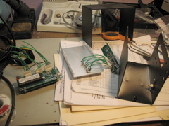
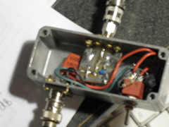
2007 September 17. The Power Meter kit
arrived from Canada in fine shape.
2007 September 22. Began construction
with the RF board. Brings back DSP-10 memories.
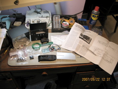
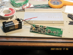
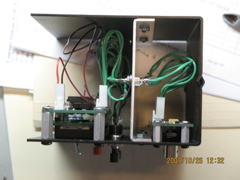
The kit laid out on the bench. The RF board right after initial
testing. Looks good so far.
So far it has taken about three hours, but that include googling "SMT solder
temperature" to decide that I should set my new Weller
WESD51 to 650 F and going off to DataSheetCatalog.com to make sure that I
was putting in the 78L05-SOT-89s in the correct direction.
This was enough time to listen to Hillary Hahn play violin concertos by Barber
and Meyer three times, and the Hindemith Requiem once.
2007 September 29 Construction
progresses. All parts for the 40 dB tap have arrived. Also, some attenuators
and a variable attenuator for use with the power meter and the next project, a
noise source.
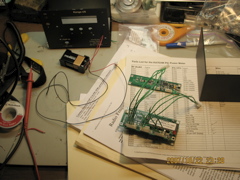
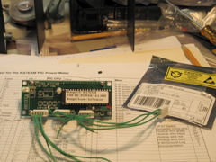
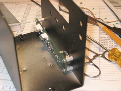
2007 October 8. 2110 - 2335 local.
Assembled all of the PIC board except for the 16 bare wires to the display.
Found that I had put in the J headers backwards on the RF board and reworked
them. (The photo above shows them "wrong.") Note: No soldering is required
to rework one of these headers. Just pull the plastic off, turn it around, and
shove it back on. I did .. one .. of them that way, after struggling with
solder wick for a while on the other and having it pull out of a couple of the
pins anyway.
2007 October 17. 2045 - 2200 local
minus 45 minutes. Put in the 16 bare wires between the PIC board and the
display.
2007 October 22. 2045 - 2300. Turned
J204 and J205 back over. My convention is that, when the plug is on correctly,
the side that says "AMP" is pin 1. Completed the cables, ready for the first
integrated test. Double checked 9V power polarity in all three places before
applying power. Should have triple checked somewhere -- smoked U101
(78L05-SOT-89) after a few seconds. Yanked the power back off. No spare
parts. Went to DigiKey and ordered
replacements for everything that might have been damaged. (They don't have a
minimum order but charge $5 handling for any order under $25. I'm going to use
more PICs, more displays, more op-amps, more voltage regulators, and maybe even
another log-power IC sometime in the future anyway, if I don't need them
here.) Still, this was the beginning of a pretty bad week in more ways than
one.
2007 October 25. 2120 - 2245. Logged in the DigiKey order and swapped out U101. Everything
seems to work! (Out of the box.) Meter gives indication of local RF noise,
-74 dBm. When I key up an HT in the room it goes to -55. Seems OK.
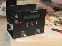
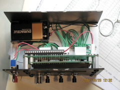
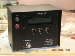
2007 October 26. 1030- 1305. (Regular
Day Off). Completed final assembly. Had trouble only with the "Mount the
battery holder using double sided tape (not supplied)" part.
Looks like it's working.
There are things I don't understand about the operation. When turned on, it
goes to blank display after booting, only coming back when a button is pushed.
Then, it seems to need to be "zero'd" (F then A) before it will function. This
could be normal. Now it's time to read the article with operation in mind.
2007 October 27. More mixed results.
Started working on the tap and, right off the bat, drilled the wrong hole in
the box. Too big of course. Thought about shims and washers for a while, then
went and ordered another box.
Worked a little on calibration and learned that my DSP-10 and Bird based
procedure won't work as I'd thought. The idea was to use the DSP-10 and
Brickette together through the Bird 43 into a dummy load and get it as close to
1 watt out as possible, noting the exact level. Then, turn it down 30 dB from
there, hook it into the meter and call that 0 dBm, plus or minus the noted
delta. Turn it up 7-10 dB and call that the top calibration point. Turn it
down 30-40 dB and use that for the low-end.
The middle and high end seemed to work OK, but there is a lot of presumably
broad-band noise in the DSP-10 output when keyed but without the CW carrier, at
least 60 dB below nominal operating levels! This corrupts the very weak
signal. Repeated using pads with better results but not good. Will need to
use even more attenuators, or something. Also, the A/D voltage on RF_ABS never
went over 2.4. Will wait for the V2.0.0 upgrade before working on this
anymore.
Corresponded with KA7EXM and got some troubleshooting hints and arranged for a
firmware upgrade.
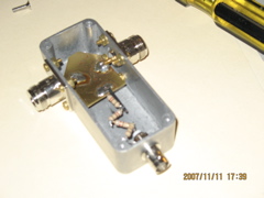
2007 November 3 1455 - 1700
local. Built the tap. Was careful with the drill. No problems this time.
Multimeter tests look OK. Predict 39.8 dB from DC measurements. About 0.4 ohm
through inline. Looks nice on the outside. Did a rough test. Worked fine the
first time. (Waited for "official" calibration to make a label.)
The 2.0.0 PIC arrived in the mail from KA7EXM.
2130 - 2400 local. Found in debugging that J204 was wired backwards. Repaired
this by reversing the wires on the top of the feedthrough capacitors through
the bulkhead. This means that the data input of U203 was exposed to 9 V in the
earlier accident. Probaby needs to be replaced. I have two in the DigiKey
replacement parts order, which has also arrived.
After this, upgraded the PIC to the 2.0.0 part. Everything works fine except
differential mode, which also implicates the U203 D/A.
2007 November 9 0900 - 0945 Pacific
Standard Time. Replaced U203. Ready
to attempt another "home calibration." I'm getting very expert at removing and
replacing the soldered-in RF board. Started into the home calibration and
found that differential mode still does not work. It appears to work from a
software point of view, but the RF_DIFF never varies much from 0.6 V. Measured
this with the multimeter and verified that the A/D is working right. Poked
around with power on and power off and reverified the U209 error in the QEX
schematic. Unfortunately, that part is right in the middle of the trouble.
More troubleshooting. All op-amps in U204 were hooked up and working right,
but the differential offset section, U204D was never being commanded to
anything but 0 volts. Determined that the D/A U203 always booted up at the 4.9
V rail and stayed there until the first ZERO command was issued at which time
it went to the 0.15 V rail and stayed there from then on, regardless. This
caused the reference on U204B positive input (pin 5) to be so low that no
positive voltage on the output (pin 7) could satisfy the divider back to the
negative input (pin 6) so it was unable to lock.
The communication from the PIC to U204 was through J104/J204 that had been
wired backwards.... Checked this four times and everything was hooked up
correctly according to the QEX schematic now. It either had to be a wiring
error or a software error. Wrote KA7EXM and got a datasheet for the AD7391
from google. Looked like it was hooked up right per the datasheet. Tried the
old 1.0.1 PIC and a spare 2.0.0 PIC. They all had the same behavior. That
would seem to rule out software. Started rearranging the three wires (DAC_LD,
SER_DATA, SER_CLK) among the six possible ways they could be hooked up,
soldering, buzzing, and testing each way. No change in behavior. Neither did
it start working nor did it stop doing what it was doing, booting to the plus
rail and commanding to the minus rail on any ZERO.
KA7EXM wrote back confirming that "300+ happy customers" can't be wrong about
the software. True enough. He offered to write sweep software if I wasn't set
up to do it yet, soon as he was unswamped at home. (Boy, I sure know about
being swamped at home!) The message arrived in my inbox ("bong") in the same
moment that I was discovering a short in the feedthrough capacitor for
SER_DATA. Yes, that would be one way to load all zeros into the D/A every
time. This was clearly going to be it, but it took most of another hour to get
the short cleared. Finally I had to take the cap out and work on it
alternating between a soldering iron, solder wick, and a sewing needle. (No
spares of this part.)
Not "Flight Grade."
Yes, in fact, this line grounded and its effect on U204B would explain every
odd operational behavior I've seen from the beginning.
I'm going to have to upgrade my construction practices.
1415 - 1630 local. Started into the home calibration again.
Hooked up DSP-10 -> Brickette -> Bird 43 10C -> Tap -> Heath Dummy
Load.
144.200.300 CW, found the DSP-10 setting closest to 2 watts on the Bird. It's
Xmit Pwr 87 which read 2.15 W consistently, 33.32 dBm. It doesn't matter that
we're into compression here. This procedure does not depend on the linearity
of the DSP-10 controls.
Reconnected DSP-10 -> Brickette -> Pasternak PE7033 -> Power Meter.
The PE7033 is a 0 - 2 GHz, 0 - 110 dB step attenuator that I got on ebay for
about 15% of its supposed list price. Plan to use it for noise figure testing
but it comes in very handy for this too, now that I understand how to do this
test.
Here are the calibration points:
PE dBm A/D Note
33 0.3 3.66 calB
23 10.3 4.12 calC
103 -69.7 0.96 calA
Note that, against the PE7033, the meter is very "linear" (that is 1.0
dB at a time +/- 0.1) from 0 to 10 dBm so I'm using a 10 dBm calC rather than 7
dBm.
Note that the calA point is very noisy. (This gets worse, see below.)
Note that the DSP-10 floor noise is something like 50 dB below the signal being
measured but that at calA, the meter itself only goes 7-12 dB lower itself.
Note that I figured out how to use the software to set the points itself.
Note that the meter reads -84.9 dBm on a terminator, give or take.
For differential mode
PE RF_DIFF RF_ABS dB relative
33 2.51 3.66
33 4.68 3.20 -10.03
Note that the sensor voltage goes into the differential amp on the
negative input (U204B pin 6). That's why a lower power is a higher voltage.
Note that a JFW 10 dB inline attenuator was used right at the meter input for
this measurement, using the PE7033 to set a usable level.
Full signal directly through the tap read -7.6 dBm. Expecting 33.32 dBm which
implies 40.9 dB tap. Set the tap calibration to that value for now.
This is all at 144.2 MHz. So then I hooked up some other rigs to spot check
other frequencies of interest.
Rig
Frequency Bird Power dBm PE 103 PE 33 PE 23 33-JFW10 Tap
405 dBm del exp. tap del. amp del. remark
DSP-10 - Brickette 144.2
10C 2.15 33.3 -70.4 0.3 10.3 -10.01 33.4
0.0 0.1 cal to this
IC T81A, 13.8 V, High 432.1
5D 3.6 35.6 -77.8 -0.2 9.1 9.22 33.9
-3.1 -1.7
IC T81A, 13.8 V, High 1296.1
2.5K 1.05 30.2 -- -63.2 -47.7 -9.74 -1.1
-57.7 -31.3 0.6 reflected
Argonaut 509 28.05
100H 3 34.8 -71.5 3.6 13.1 -9.85 37.7 50 50.2
1.6 2.9 -3.2
Argonaut 509 3.55
100H 4 36.0 -74.9 4.3 14.0 -9.83 37.2 47 48.1
1.1 1.2 -1.4
DSP-10 - Brickette 144.2
10C 2.15 33.3 -63.0 0.4 10.3 -10.07 32.9
0.0 -0.4 check cal
Note that none of this equipement (except the PE7033) is supposed to work at
L-Band. I see here that it's not even good "for indication."
Note that some ripple is expected across 0 - 500 MHz from Figure 2. of Simple
RF-Power Measurement (W7ZOI and W7PUA), variations of about a dB.
Note: "del exp" is the average of calB and calC (PE 33 and PE 23) compared to
Bird.
Note that delA (PE 103) is fairly noisy. See "check cal" for example, where
the 144.2 calibration is checked first and last.
Note that Bird readings are poor at HF, about one significant digit and maybe
even that isn't accurate.
Note: "tap del" checks the tap-based reading (calibrated to 40.9 dB) against
Bird.
Note: "amp del" is the Ten Tec 405 amplifer set against the Bird 100H compared
to what the power meter reads through the tap between Bird and dummy load.
It looks like the meter can be trusted to about 3 dB over the high power end of
its range from HF through 70 cm and maybe 1 dB at 2 meters where it was
calibrated.
It looks like the differential mode is good to at least 0.5 dB, 0.1 dB on 2
meters where it was calibrated.
With professional gear, every decimal displayed is probably accurate except as
noted. With amateur gear, we want to see beyond -- into the noise. This
device sees one or two digits beyond its accuracy.
This project is complete except for carrying the box in to work for a
higher-grade calibration there then measuring all the radios at home for
reference and experience.
1910 PST
2007 November 19. Calibrated and took
check measurements using an Agilent E4421B signal generator (calibrated to 0.1
dB). Calibrated to points at -70, 0, and +10 dBm at 144.2 MHz then spot
checked -70, -50, -30, -10, 0, and +10 dBm at each of 1, 2, 5, 10, 20, 50, 100,
200, 500, and 1000 MHz. Entered these 60 points into Excel. Zero'd at -10 dBm
(144.2 MHz) and took data ever 2 dB from -20 to 0 dBm to calibrate and check
differential mode. This got a surprisingly different answer than the home
calibration and the linearity of the plot was to about 0.3-0.5 dB. Also, hit
the rail at the high end. Applied +15 dBm through the Tap, decided on the spot
that it was 40.5 dB (at 144.2) and set it to that, then swept the above set of
frequencies. Finally, measured the loss in the six foot RG-58C jumper used at
the ten frequencies.
The calibrations are with the six foot jumper in place, not unreasonable.
2007 November 22. Entered the above
data into a spreadsheet and performed several operations.
- Made a parallel table where all the values are corrected for the six foot
cable loss. This infers levels at the input to the meter itself.
- From that table, plotted these two tables which say something about the
linearity and frequency dependence of the meter across its measurement
ranges.
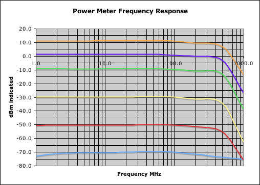
The Frequency Response chart shows measurements at each of the input levels,
-70, -50, -30, -10, 0, and +10 dBm versus frequency. Two features to note are
the sharp, expected roloff at 500 MHz and the "fuzziness" of the measurement at
-70 dBm.
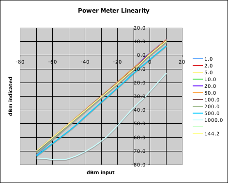
The Linearity chart traces the input power versus indicated power at each of
the frequencies, demonstrating reasonable linearity, given the nature of the
measuring device. Note that it is even linear at 1000 MHz, far out of its
range, once there is enough signal to measure. This implies that the meter can
be used "for indication" even at L-Band, for example, to determine if a local
oscillator is working at all, and to perform order-of-magnitude guesses as to
how well.
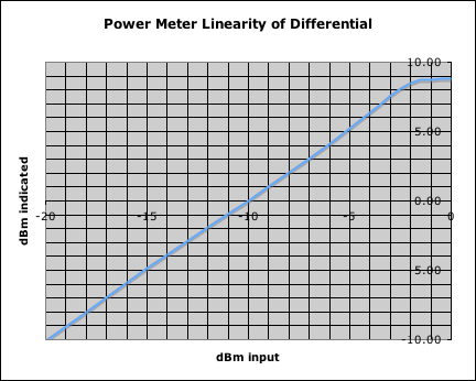
This is the differential plot.
The calibration values corresponding to these charts are:
calA -70.0 dBm 0.66 V
calB 0.0 dBm 3.73 V
calC +10.0 dBm 4.11 V
calD +10.0 dB 2.06 V
tapOffset 40.5 dB
Linearity in differential mode is acceptable, the intent being to get
nearby relative measurements within a few tenths (not hundredths) of a dB. You
can see a little bending if you look at the plot edge-on. This is doubtless
influenced by the range in which the part is being exercised and as such is
probably only representative, not definitive. This would also explain why my
home differential calibration was somewhat different, having been performed
over a different absolute range. You can also see the supply rail on the
differential op amp at the top of the range.
Finally, I used interpolation of the table to estimate what the +15 dB signals
measured through the tap should have indicated at the various frequencies. The
tap was screwed directly onto the signal generator and the six foot RG58C was
used from there to the meter. This chart shows the tap loss based on what the
meter should have read at that frequency, given that I'd entered 40.5 dB into
the firmware, and accounting for the six foot cable loss.
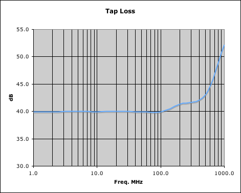
As noted above, based on resistance measurements, I had estimated that this tap
should be 39.8 dB. This plot agrees well with 39.8 to 40.0 dB through 100
MHz. It also agrees well with 40.9 dB at 144.2 MHz, which is what I had found
at home. A capacitor (short length of hook up wire parallel to the series
resistors) is supposed to provide some equalization above that, and appears to
be doing so, but not perfectly. Now that I have this chart from which to make
corrections, I'm not going to mess with the internal components anymore. As
frequency approaches 1000 MHz, the internal dimensions of the box and the
components start being a signficant fraction of a wavelength. Also, the series
resistors probably begin to have significant inductance.
In the spreadsheet with the data, I wrote up cells that do dual interpolation
(frequency and power range) so that I can convert any direct reading from the
meter into a "more calibrated" reading by simply filling in what the meter said
and the frequency. I also did this for "tap in" and "tap out" and for the
differential mode data. Based on this data, it appears that the meter will be
accurate within about a dB at the calibrated frequency, one or two dB elsewhere
(two or three at 500 MHz) and maybe half a dB when using the results tabulated
in Excel. All that I've done in Excel is a twenty-times more involved
interpolation scheme than the three-point calibration in the meter's firmware.
Sixty is doubtless overkill, but having done all this, I can now make that
statement with confidence.
The meter, teminated at 50 ohms, reads -76.3 dBm. Open reads -76.2 dBm.
Connected to my discone at 10 meters height overlooking the Los Angeles basin,
it sees on the order of -20 dBm of power from 1 - 500 MHz (filtered, of course,
by the 100-1300 MHz with 50 MHz whip discone).
I expect to be able to detect noise diode (see "Next" below) function (7000 K
at 500 MHz bandwidth), but not accurately calibrate it with this meter. It
should read about -73.2 dBm, which is detectable, but way down in the fuzz.
This concludes construction and calibration of the KA7EXM, KangaUS Power
Meter.
Immediate plans:
X Use it to re-measure everything in the shack to get a feel for how everything
is working and for how accurate and precise the meter is with and without
calibration tables.
X Use it to re-align the DSP-10 to reduce the roofing filter ripple from 2 dB
to half a dB and move the whole passband down a little so I can get "full rated
output" at 144.0.
See this story under 2007 December 15 at Phase
Two - Calibration.
Medium term plans:
- Use as a PIC project and/or as an example for other PIC based projects.
- Use for future construction, debugging, and qualification projects.
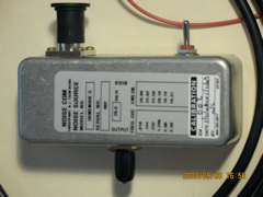
William Sabin (W0IYH) Noise Source
2007 December 20
Amazingly, the Nov/Dec 2007 QEX had a letter to the editor about parts
sources for the homebrew noise source originally described in May 1994 QST p.
37, particularly the noise diode itself. Got started in earnest on this at the
opening of the Christmas season, December 20. This is a good time for building
things, not such a good time for ordering parts, or replacing broken ones. Got
started at nearly midnight with a Mouser
order based on the QST article and the template at http://www.arrl.org/notes/hbk-templates/sabinns.pdf
. Next afternoon, placed an online order from the test equipment page of FAR Circuits
for the PC boards. You get both the UHF and microwave versions in a single
order.
Also started trying to contact Al Sebolao at Noise/Com (mentioned in Sabin's
letter in QEX) about a small purchase of the zener diode itself. Al, of
course, was on holiday and the person who was filling in for him was not very
familiar with the hobbyist offer. One salesperson local to me (southern
California, Noise/Com is in New Jersey) quoted me the minimum order of 10 for
$25.00 each. At length, Al got back from vacation and on January 3, 2008, I
faxed him an order for two of the diodes (NC302L in the DO-35 package) at the
amateur rate, $10.00 each. An assistant called for my credit card information
and said they would run the card for $20.00 plus shipping the "next day."
About a ten days later, I replaced two cellphones on the same credit card one
evening. This caused alarms at my bank and my credit card was locked down for
about an hour the next morning until
the bank called me to verify the purchases and unlocked it. During that hour, (note that this is ten
days later, not the next day)
Noise/Com ran the card and had it rejected. This resulted in more phone
calls. Soon the situation was straightened out, and the diodes arrived the
following week. DHL.
One hassle about this device is that it wants to run from 20 VDC. My MFJ
adjustable supply only goes up to about 15 V. 20 V batteries are not plentiful
around here either. I designed a circuit that would allow me to run the MFJ
supply in series with my station battery/charger supply. This only works
because the MFJ return is isolated from the rest of the station (when and if I
disconnect it from the rest of the station.)
2008 February 1
Checked in all the parts, made a trip to OSH for hardware (and pulleys for antenna work
unrelated to this), drilled the holes in the box, and mounted the switch and
connectors. The box used is the spare from construction of the 40 dB tap for
the KA7EXM power meter.
2008 February 12
Made up the power cable, twice. Misread my own schematic and made up a nice 16
guage short. I wish I had a nickel for every time I've done something like
that. Remade the 20 V. harness and tested.
2008 March 29
Soldered up all the parts on the board and in the box.
Carefully set up the 20.00 V supply and connected the source to the supply and
the DSP-10. No smoke but.... Did lots of "in" and "out" measurements. No
real discernable difference. Opened it up and checked workmanship on some SMT
resistors. Reflowed a few places. Took some more measurements. Not much
difference. Tried hooking up to the KA7EXM power meter (see above). No
appreciable difference there either.
Having had no prior experience with noise sources, I didn't know what it was
supposed to do or how "noticeable" the change between "on" and "off" was
supposed to be. Reflowed the 5 dB pad parts. No difference. Posted and
e-mail query to W6GL and W6RMK. Gave up for the night.
2008 April 8
Reconnected the source and started making voltage measurements inside while
operating. Didn't seem to be much difference between "on" and "off." Removed
the Noise/Com NC302L from the circuit electrically and noted that forward and
reverse impedances were about the same. Broke the part into four pieces
removing it from the board.
One diode down and one left. Carefully installed the second NC302L on the
board. No smoke again. Now there was 13.4 dB difference in the DSP-10 noise
measurement between "on" and "off," and the bias voltages "on" and "off" looked
about like they should (both from circuit analysis and from the description in
the QST article).
Yes!
As expected, could also read a little power on the KA7EXM meter.
Terminated the power meter reads -76.4 dBm, it's measurement floor. Fed by the
noise source it reads -66.5 dBm. Given that the power meter has around an 800
MHz bandwidth (see graphs above) and that the ENR of the source ought to be at
least 20 dB, this seemed a reasonable reading.
80 MHz = 89 dB-Hz
20 dB ENR over 290K = 44.6 dB-K
P = kBT
= -198.6 dBm / Hz-K + 89 dB-Hz + 44.6 dB-K = -65 dBm
Since the device was not yet calibrated, didn't concern myself with what the
13.4 dB difference in the DSP-10 receiver might mean.
2008 May 9
Called Noise/Com (973.386.9696x4106) and left a message. Also sent an e-mail
asking for authorization to send the box in for calibration.
2008 May 14
Received a request for an RMA (Return Merchandise
Authorization) from Noise/Com. They made it clear that for $100 (plus shipping
and handling) I would get two
calibration points.
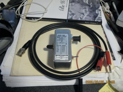
2008 May 15
Boxed up my noise source and power cable with the PowerPole shorting plug that
allows a shop with a 20 V supply direct to banana plugs for use without ganging
supplies. Wrote a nice note saying that if I could have only two points, 144
and 432 MHz would be it, but this would leave me curious about 10 and 1296 and
the rolloff above 2 GHz. Called it S/N 002, inasmuch as it contained the second NC302L.
The calibration was performed at Noise/Com on 2008 May 21 and I got the unit
back several days later with a sticker on the box, caps on the connectors, and
a nice calibration certificate with the following data on it:
F. GHz ENR dB
.010 26.80
.144 24.02
.432 22.50
1.296 20.10
2.00 19.19
2.50 19.37
Flatness 7.61
RSS Uncertainty on the standard used +/- .18 dB.
Utilization of the calibrated noise source continues at Phase
Two - Characterization on 2008 September 6, nearly a year after the failed
"heat and cool resistors" test.
W1GHZ DEMi All Band
Power Meter (ABPM)
2010 April 14
The KA7EXM
Power Meter tops out at about 500 MHz because the AD8307
part it's based on only goes to 500 MHz. Good sensitivity but not L-Band (1 -
2 GHz). So as soon as I had all this test equipment set up, I started into an
L-Band project and needed more equipment.
When working on the 1296RSU converter and the DEMi 2330PAK amplifier I need
something that would go to at least 23 cm, that is 1.296 GHz, that is
L-Band.
Down East Microwave has such a product in the All Band Power Meter (ABPM). I
ordered the kig and decided to build it before working on the 23 cm gear any
further.
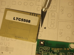
The ABPM consists of two power sensors, an LTC5508 for UHF (0.3
to 10 GHz) and an AD8307
for VHF (0.00001 - 0.5 GHz). The user uses a different input connector for
each, calling them UHF and VHF respectively and must remember to throw the
switch on the outside to the appropriate input (or be prepared to panic).
There is a built in ten LED display for approximate indication and a jack for
connection to an external volt meter for higher precision.
2010 April 21
After checking in the parts and pre-reading the instructions, the very
first step is to mount the most difficult part, the LTC5508. It is about the
size of a fleck of pepper and is a six pin package. It requires a great deal
of study just to see where on the board the pins should go. After 90 minutes
of tedious, microsopic work, I had a first failure. I had shorted pins 1 and
2. Removal of the part was destructive, then I lost it somewhere in the room.
Although the floor is linoleum, it has a texture that hides pepper flecks well
and there are many crevasses and boxes around the bench that make the search
into a low probability activity. After any sweeping, or the cat walking by,
one should simply give up.
2010 April 22
Reverse engineered the installation problem, wrote a procedure for how to do it
correctly again with the proposed pin soldering order of 1-4-2-3-5-6. Ordered
six more fleck-of-pepper-sized parts for $3.44 each from DigiKey. After the removal, the board was
not in great shape so I was confident that it would take at least one more
try. I didn't ever want to be working with the "last part I had."
Of course, a stop like that causes everything to be delayed for months. Life
happenes. Another reason to buy extra on an order.
2010 July 24
Months, like I said.
Lost two more parts just handling and doing placement, now down to four. Noted
under the "microscope" (inverse binoculars, see picture at 2004 March 11 of Phase
One) that the solder on the board was pretty unacceptable and
unmanageable. Did what I could with a needle solder tip and braid that wasn't
small enough, then took it out to the garage and burnished it lightly on the
grinder. Aside from leaving some burnishing marks, it looked, and tested
electrically, like it might still function.
The fourth part went down in 90 excrutiating minutes starting at 2210 local.
Pin order was 6-3-1-4-5-2. Five and two were very tough to do. All shorts and
conducts were tested at each stage. Looked good. Ready for step 2 at twenty
past midnight. Quit.
2010 July 30
The remainder of assembly was comparatively straightforward and after about
five hours I was ready to start on the enclosure work. Ninety minutes after
that I noted that the SPDT switch was missing from the kit. Unclear whether I
had lost it or it was never there.
2010 July 31
Went to Radio Shack for a mechanically compatible SPDT and
found one for a nominal price. Installed and completed assembly up to the
first-smoke stage. Everything worked fine except that the LTC5508 had 0 V
output under all conditions. The inputs I could measure looked OK. Inspected
closely and saw a bubble on the pins 6-1 end. Removed, taped the fleck to my
note sheet, and cleaned up the board again. Ready for try #4.
Order this time was 3-6-4-5-2-1. All went well. The shorts stayed clear and
the conducts kept working solder by solder (buzzed out everything at each step)
until at the very end (another 90 minutes of effort) when pin 1 broke off. Ran
a fly wire - one 3 mm long strand of some stranded #20 to attempt a repair.
Very rough.
In less than two more hours I was finished, including labels, and taking the
meter around testing it on everything - the discone, the microwave, the LO in
the 1296RSU.
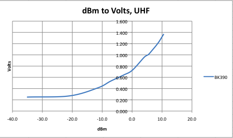
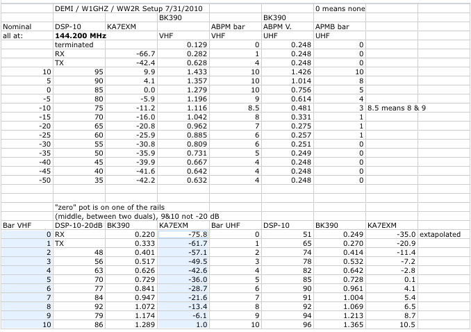
Did a a self-calibration on 144.2 MHz, both inputs, comparing to the calibrated
KE7EXM meter with these results. My AD8307 is not as sensitive as the W1GHZ results and
the VHF curve is a little flatter per bar and per volt, but the UHF data (from
the LTC5508) is in excellent agreement. At least at 0.1442 MHz where I'm
equipped to generate calibrated signals and up through the + 10 dBm that the
DSP-10 will put out.
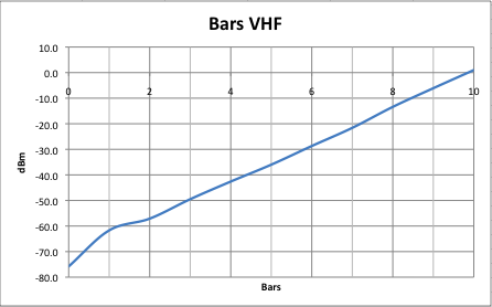
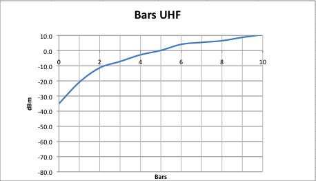
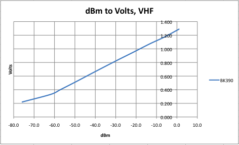
The data:
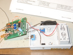
The DEMi / W1GHZ ABPM in final assembly.
n5bf/6
DSP-10 page
n5bf-at-amsat-dot-org
updated 2010 September 6, cbd