DSP-10 Software Radio
Construction of Unit I, Brickette, and Early Results
back to n5bf/6
DSP-10 page
Brief pre-History
When I was in High School in a small central Texas town in the early
70s, I got started in ham radio.
(See amateur
radio biographical info..)
It wasn't long before I realized that all those new logic circuits
(like TTL 7400 series) could be put together into anything shifting
the burden of a complicated signal processing circuit (and its
debugging) to "software" (after a fashion, maybe "design ware" if in
NAND gates). It became a loose dream to eventually
have a radio that would be mostly software rather than expensive,
tricky, cranky hardware.
Skipping past a whole lot of non-radio biography, we come up to the
period 1981 - 1991 when I was increasingly involved in AMSAT-NA, eventually becoming their Vice
President - Operations from 1988-1991.
(See <future AMSAT autobiographical link>.)
One relevant episode leading up to that period was in the late 1980s
when AMSAT and TAPR
members did a joint buy of Dalanco Spry DSP processor boards that would
plug into PCs. This was in the era when the typical sound from a
computer was just a beep and the typical CPU speed was 5 MHz. The
Dalanco Spry boards featured a TI 32010 DSP chip at 25 MHz which would
allow easy, integer processing of audio to and from ham rigs. I
bought one of the boards, but the group soon realized that we could do
more with them if we had documentation which was not amply provided by
the manufacturer, not at the amateur price, anyway. Paul
Williamson, KB5MU, and I set to work to produce a set of
schematics. Using an ohm-meter, I buzzed out all of the traces
and connections and e-mailed the information to Paul who laboriously
drew up the circuits and made prints. In a few
months, we had what we needed. Meanwhile, others were doing
on-the-air experiments to put their Oscar-class stations into
moonbounce and over-the-horizon DX operation, something not widely seen
before.
While an AMSAT official, I had one more chance to use the board.
Dick Allen, W5SXD and Joe Bijou, WB5CCJ, authors of Graftrak satellite
tracking software, wrote software for this board that would track a
carrier from an amateur satellite and record a set of doppler
data. They also had a program that would process such data,
estimating the position of the receiving station. I made use of
this to fix my station location to within 4 km (Dick said I got lucky)
and presented this among many other forward-looking ideas for amateur
satellite enthusiasts to pursue as part of a talk at the 1989 AMSAT
Symposium.
All this was done on a true-blue IBM XT which was retired within a few
years. The next time I tried to use the Dalanco Spry board, the
new 486-33 SX system I had wouldn't even boot up with it plugged
in. There was some indecipherable incompatibility and the board's
days were over for me. (Paul had gone through this somewhat
earlier than I did.) If I was going to do anything useful with
such hardware, I was going to have to work on it faster!
The problem with AMSAT leadership was that I was spending 30-40 hours a
week on ham
radio (after work hours of course) and it was all politics -- phone
calls,
e-mails, shmoozing, begging, etc. I was having no fun. I
was not building anything. Or programming anything. I quit
the political position, sold all those appliance radios that constitued
my satellite ground station, and took a hiatus from ham radio.
At that point I promised myself that when I got back into VHF and above
it would be via a construction route. I daydreamed about
hardware designs and software architectures.
Skipping up to late 1999, Bob Larkin W7PUA published the design for a
software IF, 2 meter radio in QST. The receiver was good, the
transmitter was 40 milliwatts, a little low for a line-of-site
band. The intent was that this would be the driver or IF for
other VHF/UHF work or you'd put "shoes" on it and use it as a 2-meter
rig. I immediately saw that this was going to be as close as I
would get to my daydreams on this subject. The rest is discussed
below.
Construction - The Blow by Blow
1973 circa - Had the original
software radio idea on the South Padre
Island (Texas) beach on a summer vacation.
1999 September, October, November - QST Construction and Description
Articles
1999 October 7
- Ordered $99
EZLITE
1999 October 20 - Got in on the
initial AMSAT kits buy managed by Dan
Schultz, N8FGV
1999 December 12- Joined DSP-10
mailing list at qth.net
2000 January - Received Kit --
DSP-10 Rev C, Rev 4, 1999 September 20.
2000 April - Announced quest to
buddies and started saying "no, I'm not
going
to do <whatever> until I do it on DSP-10"
2000 July 8 - Started up a nice
big notebook.
2001 May 18 - Placed Jameco and
DigiKey orders for soldering iron,
tips, surface mount handling tools, etc.
2002 September 9 - Began
construction with W2, W3, and W11.
2002 September 19 - Finished
wires with W24.

2002 November 15 - Ordered 2nd
DSP-10 kit from TAPR.
2003 December
New JPL ARC President W6RMK challenges members to
"finish up that project" in 2004....
Made a weekly progress plan. (What a waste of time!)
2004 February 11 1930 PST -
Finished resistors.
2004 February 28 - Placed
Jameco order for static pad, wrist strap,
more tips, and a
Kg of solder.
2004 March 11 2115 PST -
Finished chip capacitors. Burned up a
soldering tip by leaving it on for 48 hours.
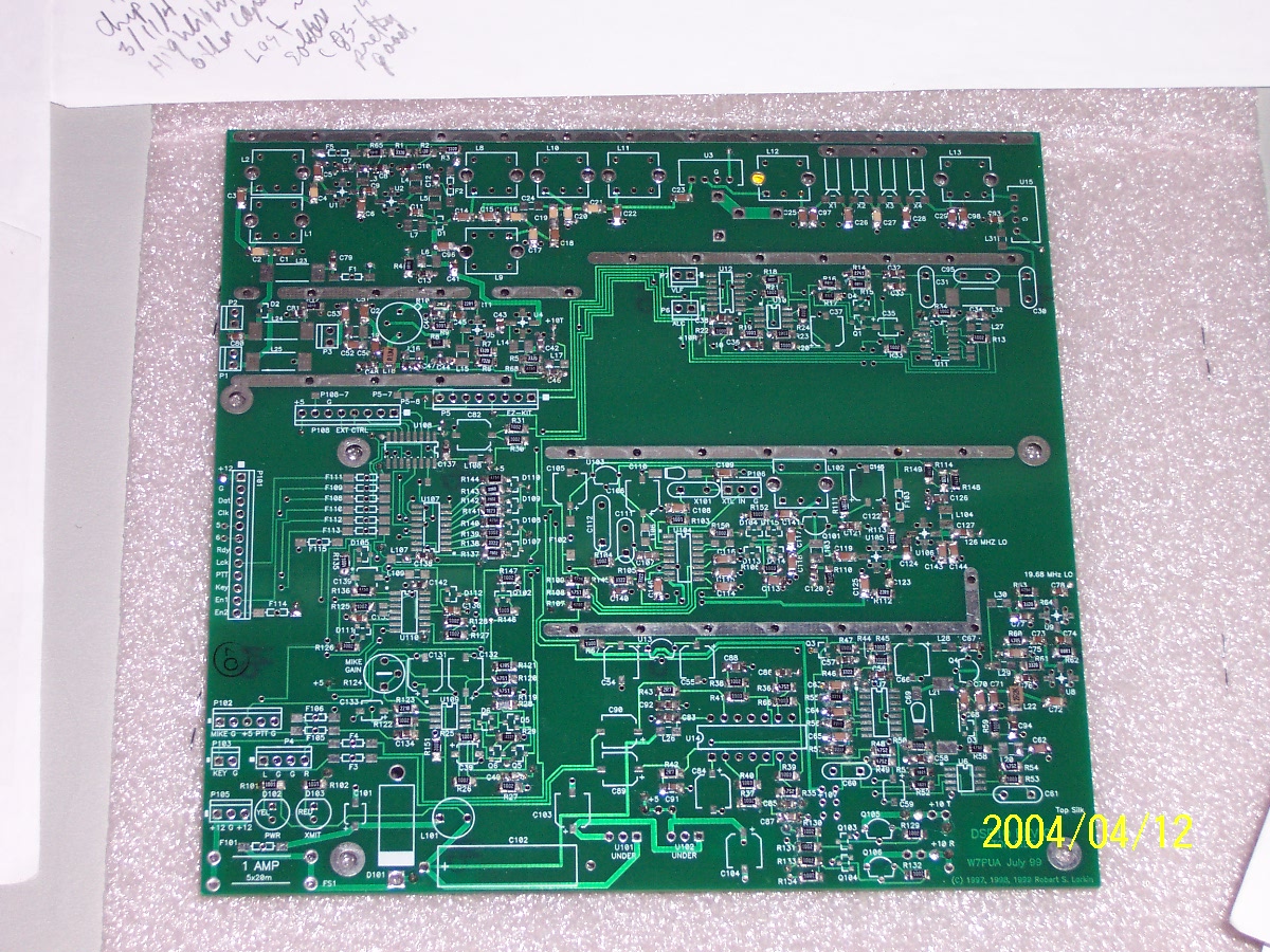
Inspect every solder under the "microscope".
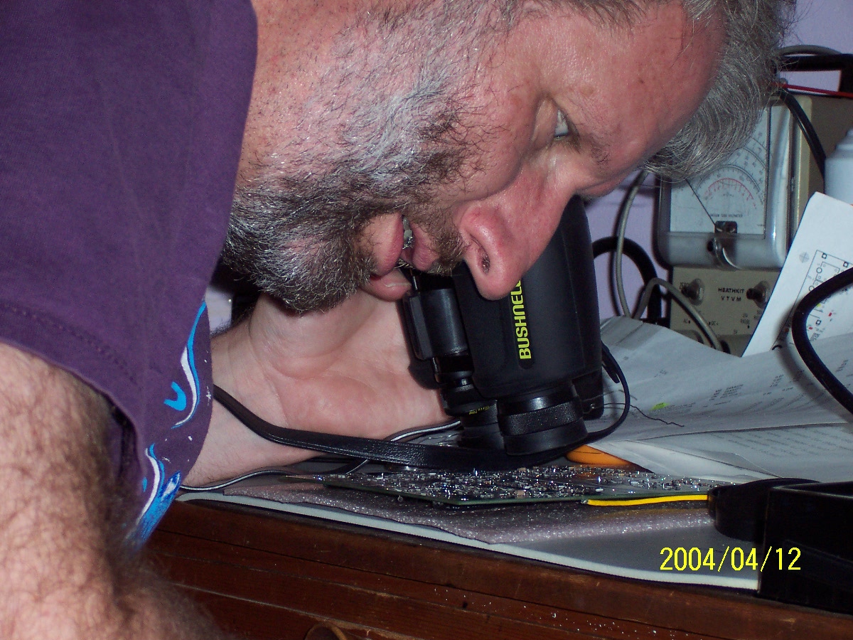
2004 April 13 2015 PDT -
Finished chip inductors.
2004 June 25 about midnight -
Finished all chip parts, now have to open
the "bags".
2004 July 21 - Wound but did
not install the toroids.
2004 July 24 - Finished small
bag #2 including the 5 hand-wound
toroids, U7, and a couple of switch transistors.
2004 July 29 - U201 and ten
ferrites are left over ... oh, they're for
the EZLITE and interfaces.
2004 September 17
Finished RF board.
2004 September 18 Initial
smoke test, connected TCXO.
Repaired errors (switch transistors in backwards) and recent mods.
2004 September 19
Replanned: 12 hardware sessions (plus
debugging) to "on the air" status. Full page of SW ideas.
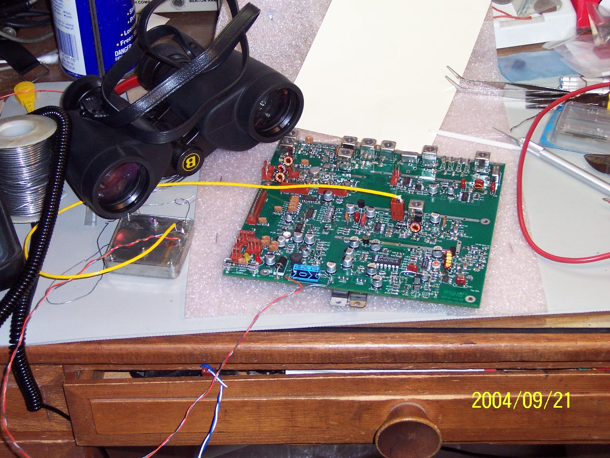
You can see the "don't transmit and receive at the same time" diode
there in the front just right of center, "flying"
and the yellow "power on" light illuminated, front left. No
smoke! Once a week work plan now caught up through April '04.

2004 September 20 Wire up
TCXO
2004 September 21 Smoke
Test. (No Smoke!) Realized I
could go no further without EZKIT interface working.
2004 September 23 Placed
orders with Mouser, Digikey, Jameco, and
West Coast Mall ("CB
Microphone")
2004 October 12 Bought
some new drill bits at Orchard
Supply Hardware.
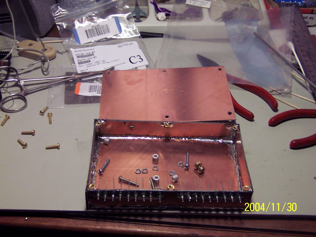
2004 November 30
Construction of Faraday box for EZKIT Lite
nearing completion, note the expensive feedthrough caps.
2005 January 4 Converted
a 66 MHz Windows 95 computer to DOS only
- to be the "front panel."
2005 January 5 Ordered
RS-232 cables and swithbox from Cable
Wholesale. (Kids at
Office Depot had never heard of "RS-232"!)
2005 January 7 Talked to
EZKIT Lite for the last time from the
DOS only box before making "minor mods."
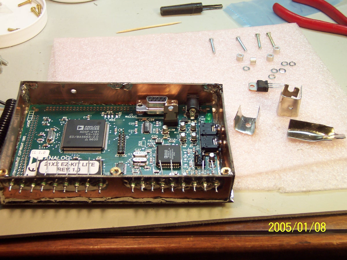
2005 January 8 Began "Intensive" to finish construction and make
that first QSO.
2005 January 8
Added a "dot paddle" input so I could do keyer
software "someday."
Mechanical rework in an attempt at final
mechanical assembly configuration. (Only 2 of 4 mounting holes fit.)
Tore off concave audio end wall and reversed. Ughh.
Carved a computer backplate into three heat sinks
for regulators.
Moved feet from EZKIT Lite board to main box.
2005 February 8
Removed EZKIT U6 (regulator) and reinstalled at a
slant so that it and its heatsink would fit in closed box.
Finished all Faraday internal wiring except the regulator (power).
2005 February 15
Removed three (of six) lid screws and replaced
with solder wick "hinge" straps
"Rear screws wouldn't fit with board in place.
2005 February 21
Coax connections to main box connectors (Ant
211, 10 MHz 206, etc.)
Reverse engineered CB mic. and changed PTT from "RX high" to "TX
ground". Good Grief.

2005 February 24
Finished internal wiring harness (old telephone
cable wire). Ready for testing.

2005 February 26 The Debugging
Begins
2005 February 26
First integrated power up.
Something wrong with 10 MHz TCXO signal.
No 10 V regulated (or 5 V) on RF board. Repaired broken 10 V
regulator leads. (Those screws didn't fit either.)
EZKIT Lite boots and talks to DOS computer! This is a major
victory (and relief) after all that cramming to get it in the box.
Disassembled for 10 V regulator repair.
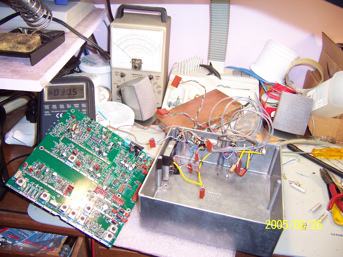
10R not working, cleared solder splash on Q104.
19.68 MHz is 21.006 and 124.5 MHz is 100.626. This is not a "two
meter" rig yet.
Gave up at 1:05 a.m. local (2/27/5)
2005 February 28
L21, added turns, spliced turns, took off turns,
tuned through 19.68 without locking. Rail to rail on PLL.
Posted problem to list.
2005 March 2
Repaired ground on 10 Mhz. Start with
udiag2.exe. Great program but no joy in my box.
No output on U104-2.
U107 not loading right, go to udiag1.exe
2005 March 5
Checked about 30 signals using
udiag1.exe Found U108-9 not connected to U107-14! (Shift
register out to in!)
Connected with a jumper and added the 470 pf across U107-14 to -8 as
advised just to be sure.
U104 is probably now loading bits but VCO is still 100.474 MHz..
Removed slug entirely from L102, grounded C113-R105 junction
->123.62 MHz. 5V -> 129.07 MHz.
Should be working .... looked at every pin on U104, nothing on pins 2,
14, 13, or 7. Posted to the list again.
2005 March 7
KD7TS suggested AC coupling TCXO (to U104-1).
Redesigned and reimplemented.
U104 now works as specified, locking on 126.00 (udiag2.exe). R105
at 1.205V. Yes! Thanks
Mike!
Deferred the 10 pf to 6.8 pf swap on C117 until I could get a part.
Back at 19.68 MHz, L21, added a turn, took out a turn, remounted L20
(cold solder joint).
Cleaned up around D3, tuned low, took a turn out of L21 -- locked!
Put RTV on L21, C69.
Loaded uhf3.exe and talked to it from an HT on FM. Now it's a 2 meter rig. 0745Z
3/8/5
2005 March 8
D2-A1 test failed because D108 A1, A2 not
soldered. Fixed.
Could hear 147.36 repeater off air only by shorting J211 (ant) to C23
(1st mixer)
(Or by putting a scope probe on the first mixer, hi....)
Peaked up L8, L9. Now could hear through the front end and peak
it up too.
FM sounds good ... but
Can only barely see carrier (in CW mode) for WR6JPL 147.15, four miles
away. Hmmmm.
2005 March 10
Did the "DSP-10 U15 Mixer Ground
Modification" Measurement went from 1dB to 6 dB. Yes!
But, still essentially deaf.....Noted that pushing down on L2 while
trying to peak it increased RX
levels about 50 dB.
Disassembled the box, removed the RF board, reflowed connections to L2.
Cleaned up J203 miswiring.
Reassembled.
Now I can hear 147.09 Catalina repeater, 30 miles away with just a
little white noise.
Aligned by ear.
Mic. gain is very low, nearly imperceptible. Was "deaf", now is
"dumb"
Ordered the very last Brickette board from Beb Larkin, W7SLB.
2005 March 14
Built an approximate version of the power meter
from scrounged parts.
All DC voltages OK.
No output --- reversed P2 and P3.
CW outputs as expected, 20-40 mW. Called "CQ TEST" once at 0630Z
3/15/5, no answer.
2005 March 16
Found R124 (mic. gain) installed sideways.
Instead of 0 - 5K - 10K, it was 0 - 2.5K - 0.
Destroyed U109 in the process.
Ordered a new U109 (actually, 3) 6.8 pf for C117 (actually 10) and most
of the parts for the Brickette (except toroids) from Digikey.
Ordered the Brickette module from RF
Parts.
2005 March 23
Digikey
order came. Disassembled everything again.
Swapped C117 for 6.8 pf. Reinserted slug in L102.
Removed U109, wired new pads for -1, -2, repaired open between R124 and
R151.
Installed new U109 (385 dual op amp), carefully buzzed out all pins,
set R125 to middle, 5K.
RTV on remaining toroids. Reassembled everything again.
Adjusted L102 for a 143.0 - 148.7 tuning range, giving 2.5V on 147 at
R104/R105 junction.
CW TX gives 321 mV on homebrew power meter. Singing into mic. on
USB gives 85 mV.
Turned up R124 and software mic. gain all the way, saying "four" into
mic. now gives 333 mV.
Powered down and closed out, putting the screws in the box lid for the
very first time!
Found that EZKIT regulator shorts the lid of its internal box
intermittently.
Disassembled and put electrical tape in the Faraday box lid.
Reassembled and put the screws in the box lid for the very second time!
Found 144.700 / 145.300 repeater does not require PL, at least tonight.
Was able to kerchunk and hear my audio coming through.
Nobody there, no QSO. 2306 PST 3/23/05 is 0706Z 3/24/05.
Here's the scoop on the microphone. Radio Shack no longer stocks
RS 21-1172 or any replacement
CB mic. It is barely supported on their website, but the pinout
and specs. are still available there. The kid at the my local RS
outlet offered to sell me a CB radio
from which I could canabilize the mic. I declined.
Please!
Without any better compatability information than that it was dynamic
and had a 5 pin plug wired like Radio Shack, I bought a Barjan 325-505
from West Coast Mall. I
could find no information on it, even in the packaging, but based on my
reverse engineering and operation, it does appear to be pin and
spec. compatible with the RS 21-1172.
2005 March 26
Used beacon mode to call 'CQ CQ DE N5BF N5BF AR'
every minute for several hours on 144.2006 CW.
No QSO yet. 20 mW to a discone at 30 feet is not very impressive.
Anticipating "Calling Frequency" flame when somebody does hear me.
Oh wait. The microphone low level problem still doesn't seem
right. Investigated further.
Should I write a QST Op-Ed piece about how CW really is essential, or
should I fix this?
After a trip to RadioShack.com and reviewing my notes, it hit me.
Two problems:
I had originally wired up according to Figure 11 in QST, not the
corrected "Addendum for Rev 4.4, 10 Nov 99"
I had wired pins 1, 4, 2, 5, 3 in 3, 5, 2, 4, 1 order. Need I
comment further?
Drew up corrected diagrams and fixed everything. Now the
microphone makes sense, un-re-engineered it.
It works and to get 1 V clipping at the ADC input when shouting, R124
is set to 1756 ohms. Much better.
Yes, this involved putting all 8 screws in the outer lid the very third
and very fourth times. And messing with the DSP box again.
Back to calling CQ (CW) on 144.2006, trolling for that first flame, er,
QSO.
Operation
2005 March 17
In 1991, when I retired from AMSAT, I sold my
satellite beams to Eric Archer, N6CV. In mid March 2005, he
decided to get out of that business and posted a note to the JPL ARC
reflector that they were available to anyone who would use them.
I immediately replied with a description of the serendipity of this
situation and went over to pick them up and bring them home the
following Saturday.
2005 March 29
0345Z It wasn't that long anticipated first QSO, but it nearly
was. I had been automatically calling CQ for 20 minutes when W6RCL
heard something and started trying to answer. Of course, I could
hear him fine on USB, 52. I made specific CW calls and he would
come back saying he was hearing something "wispy" but wasn't making out
a callsign. When he started offering to get in the car and drive
around until he got strong enough signals to make it, I quickly
declined and went QRT, not wanting to put him to that much
trouble. Although Alan's QTH was only three or four miles away,
it was up a valley and not in direct view from mine. But I have
to give it to him, that is true ham of
the year spirit!
0515Z First
QSO! WA6OWM, Ray, Redondo Beach,
DM03 (30 km). 144.2006 MHz CW, 0.020 watts, discone.
Exchanged 559.
Status - Operational at 13 dBm
2005 April 16
0200Z Worked W6GL on FM briefly as he drove by on
the freeway (about 200 yards away).
Dug a hole and re-erected my 14 foot telephone pole which
I've used for satellite antennas for 25 years in three locations.
Ordered a Channel Master antenna rotator, some RG-8 foam,
some rotator cable, and a small TV antenna from Amateur Electronic Supply.
Caught up with e-mail following construction intensive.
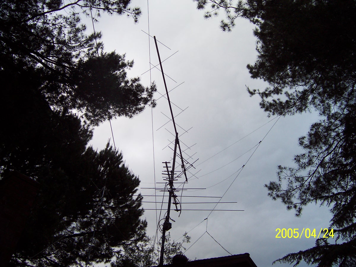
2005 April 25 Two meter
beam is back up at about 25 feet.
That's the new TV antenna under it.
2005 April 28
0333Z Using beam, checked into a local net on
144.240 USB assisted by WA6OWM, Redondo Beach (30 km). Also took
reports from W6CRO, Norwalk and KG6KUB, Altadena. Not copied by
net control.
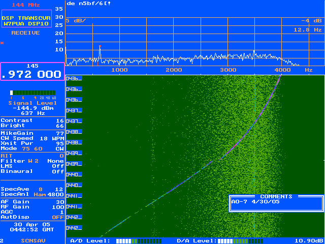
2005 April 30 Captured a pass of AMSAT-OSCAR 7
on the very first try. Mostly carrier, a little on/off switching
but not CW.
The Brickette
2005 June 4
Started mini-intensive to build the Brickette and get it
going in time for the ARRL VHF QSO
Party June 11-13.
Began with an inventory of parts.
Discovered that most of the
chip resistors and capacitors(the ones not mentioned in the sidebar
of the QST article) had not been ordered.
Placed a Mouser order at
midnight. $18
plus $13 shipping for 2nd day delivery. Expect receipt June 8.
Made a 9 Step task list. Estimated 50% chance of being QRO for
the QSO Party.
2005 June 6
Began construction with the diodes and capacitors I already
had, plus fuse clips.
2005 June 7
Completed installation of all the parts already in hand
plus three jumper wires.
Now ready to drill holes in the box.
2005 June 8
Mouser order
arrived. (Accidentally shipped 100 .01 caps rather than 10!)
Choir Concert at High School. No construction.
2005 June 9
Rode bike from work to Orchard
Supply Hardware
to buy a bunch of brass 4-40 hardware. (10 km)
Checked in Mouser order.
Drilled LED holes.
Discovered that, although there is no R27, R28 is 1K! No 1Ks in
inventory!
Put two extra 2.2K chips edgewise on the R28 pads in parallel.
Measured 1.08K. Plenty good..
2135 local (PDT) done with board work
Still need a 5.5 OD 2.1 ID chasis mount power jack. Check radioshack.com. They have
them in my store.
List remaining tasks. Estimate for QSO Party still 50%.
2005 June 10
Rode bike from work to Radio Shack. Bought
both form factors of power jack.
Got home at 1900 local (rather than "early"). Used a "Domestic
Tranquility Chit."
Started drilling holes. My 20 year old drill died. All the
bits are trash anyway.
Drove to Orchard
Supply Hardware and picked out a new 14.4 V cordless drill while
"closing time" announcements were being made.
Also bought
new bits.
Drilled (what I thought were) all the rest of the holes. New
drill is nice. Happy Father's Day.
Start mounting jacks, then board.
Oops, there are 5 holes in the board. Carefully drill another one
with the board in place. (Arghh.)
Oops, phono holes are too small. Carefully widen with everything
in place. Clean. (Arghh.)
Make up control and power cables.
I can still make it by 1800 UTC tomorrow (1100 local) if nothing goes wrong.
2005 June 11 Midnight
(continuing from 2005 June 10).
0130 local
DSP-10 J208 control voltage check, nothing.
Jack is wired backwards. Change my two wire jumper
instead of the 8 wire jack.
J208 and Brickette control jumper are now compatibly incorrect (reverse
pinout).
0135 local
First power up. No smoke. Good.
13 - 15 mA at 13.5 VDC. Good
Yellow
LED is on. Good.
Photo (Actually, this is the next day during DSP-10 re-tweaking for
more power but it's the same idea.)

2005 June 11 (continued)
0200 local (PDT)
Hooked up DSP-10 RX through relay and jacks. Reception still
good. Good.
See Over Voltage LED at 13.62 with R15 wiper on 5.13 V. Good.
Set R15 wiper to 4.68 V as specified for 14.5 V supply Over Voltage
indication.
Learn that "Alt" is manual key on DSP-10. Nice.
CW Power to 0, check. All hooked up, check. 145.990 to
avoid birdies, check.
Dummy load and Bird Wattmeter slug 5D, check.
(I realize I really need a Bird 5C. I only have a 250C! 5D
is "close enough" for this.)
Rx 27 mA. Tx 138 mA. Good.
Relay operates. Good.
Tx LED operates. Good.
Start power up 10 dB at a time.
First action is at 50, 136 mA (rather than 135 mA) draw.
First Bird action is at 70, .1 Watt @ 226 mA draw. We have
amplifier!
RF and SWR lights at 80, .5 Watt @ 514 mA draw. Good.
Started messing with L2 and L3 windings to extinguish SWR light.
This went fine for a while.
At 89, 3.7 Watt @ 1028 mA draw, impossible to extinguish SWR light.
Tried winding arrangement, coil positions, even L4 and L5 tweaks.
No joy.
Futz'd around for an hour. No joy. So close!
Removed L2, L3, L4, L5, unwound one turn from each.
Trimmed. Reinstalled.
At 100, 5.0 W @ 1515 mA draw.
Adjust L2, L3 winding (and position a little). SWR light
extinguished!
0412 local
It's working! The kids come in from a party,
worried that I'm still up.
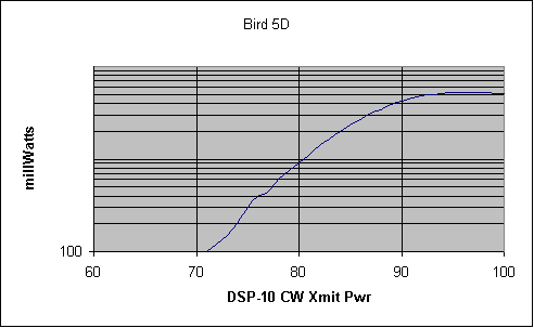
Made a chart of DSP10 setting, Bird forward power and mA draw from 100
to 71 in steps of one.
(Couldn't make Excel put anything other than "100" on that axis.
It's 100, 1000, 10000 mW.)
There is indeed no point in going over "95" drive, except to waste
current.
0429 local (PDT) Put on lid, put in operational location.
(Picture below. Note stereo speakers. Swan Mark II, on loan
from W0RPK, not involved.)
To beam antenna.
Hit 147.09 Catalina repeater on 0.5 watts. Good. (Goes down
to 70 at heading 170)
Hit 145.300 repeater. Good. (Goes down to 79 at
heading 170)
144.200 CW, 5 forward, 2.6 reflected. Gets SWR light.
Good. But why > 4:1?
Discone also shows high SWR. Make a new list of things to do.
0450 local e-mail status to W6GL.
0505 local Shut Down at dawn.

2005 June 11 (later in the
local day)
ARRL VHF QSO Party Day. Up at 1130 local. Test
in progress.
Consider modifying DSP-10 for "Fast PTT" Decline for now.
Measure voltage to the RF module during transmit. 13.05 RX, 12.87
TX, 12.40 @ 5 W out. Seems OK.
Start into contest. Make several USB QSOs on and around 144.200
calling frequency. Good!
Take lid off of DSP-10 and repeak the filter chain. All is OK, no
improved power output.
Climb up on roof with beam aimed in a direction where I can reach
driven elements. Wiggle feeds, remake connectors.
Lower discone. Straighten "cone" elements. Remake
connectors.
Back in the shack. Both now take power, >5.0 W. forward, <
0.1 W. reflected. SWR LED extinguished!
Continue making QSO Party contacts as available through Sunday evening.
Final total: 30 DSP-10 / Brickette QSOs in four grids, DM04
(mine), DM14, DM03, DM13.
(If I had been more available or if people wouldn't run the calling
frequency, could have also worked San Diego DM12.)
Write temporary labels in permanent Sharpie. Will clean this all
up some day.
Also got drug off to 6 meter USB, 220 FM, and 440 FM for more QSOs and
band/grids.
2005 June 17 1818 UTC, heard
Russian being spoken on 145.770 at a time
and beam
heading consistent with the International Space Station.
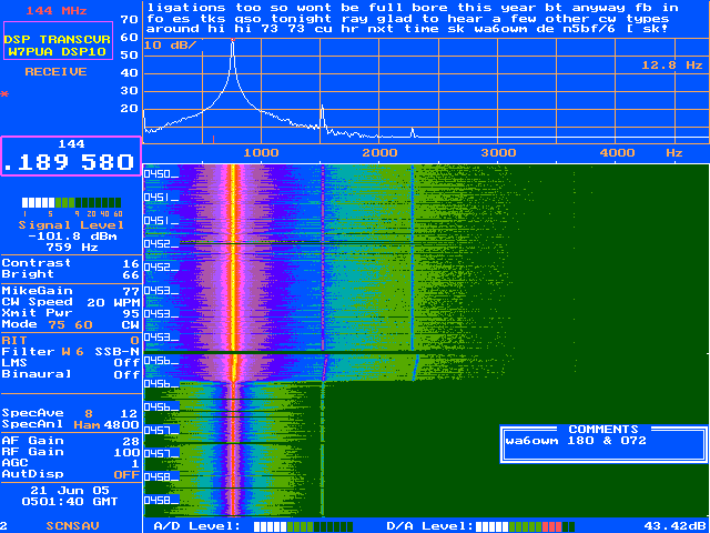
2005 June 21
0435 UTC Worked Ray, WA6OWM, DM03 again on CW
but now at 5 watts. Good report. Nice QSO.
This is the waterfall. Stronger at heading 180
At 0456 somebody wanted to watch TV so it went back to heading 072.
2005 June 23 0303 UTC
Checked into the local weak signal net
run by Gabrielle in Pomona, KG6HMN on 144.240.
Status - Operational at 5.1 watts on 2 meters
2005 June 24 0300 UTC
Checked into La Canada PERCS net on
144.465 FM with KF6DKA, Frank, as NCS.
Two attempts (weeks ago) at 20 mW were met with reports of "only
noise." This check in was totally nominal.
(PERCS is Public Emergency Radio Communication Service, a local ad hoc
group.)
Repeated exciter power measurements, posted questions to the
list. Brickette should be 7-8 watts, not 5.
My Figure 12. RF detector is 3 dB below the one in QST also:
Mine Fig. 12
mW
mV mV
20
253 491
10
67 225
5
8 66
This information extrapolated from Bird measurements.
2005 June 25 DSP-10 Only
Field Day with twelve phone QSOs.
None on CW, one nibble.
2005 July 5 Broke down
and ordered another module and a Bird 10C
(the right slug) from RF Parts.
2005 July 7
10C arrives, shows output at 6.5 - 7 watts. That's
good but need more testing.
Rewired 13.8 supply in an attempt to get more than 12.4 VDC on the
module at full output. No luck on voltage or power.
Status - Operational at 6.0 watts on 2 meters
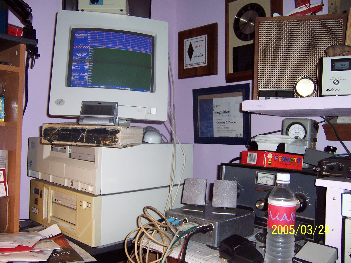
"Fully functional and ready", in the "learn how to use it"
position in the shack. 13 dBm mode
n5bf/6
DSP-10
page
n5bf-at-amsat-dot-org
updated 2005 August 24
slightly 2013 August 31
