DSP-10 Software Radio
Characterization and Operational Familiarity
back to n5bf/6
DSP-10
page
Status: Operational at 6.4 watts
2005 July 16 2223 UTC
KG6IYN, Bruce, 58/59 from DM12 in the CQ VHF WW. 8 miles north of
Mexico at 4900 feet.
Reports in all the contests indicate that nobody can tell this isn't a
storebought rig. They have no trouble copying, they either say
nothing about the audio or say it is good. They sometimes ask if
I have "other bands on that radio."
2005 July 27 Forward
upper driven element on 2 meter satellite
beam found broken (by SWR LED), needs to come down.
2005 Aug 13 0045 UTC
KG6KUB on 144.200 USB 6 watts. Fred on East Mountain, Catalina,
hiking portable, listening for KH6 beacon.
Order an M^2 2M12,
twelve element 12.8 dB 19-1/2 foot beam from Amateur Electronic Supply.
This is expected to improve my signal by one S-Unit. Also
lower receive noise on SSB.
(Can still use discone for vertical / FM.)
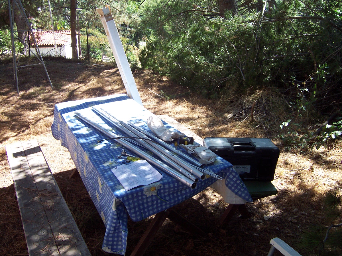
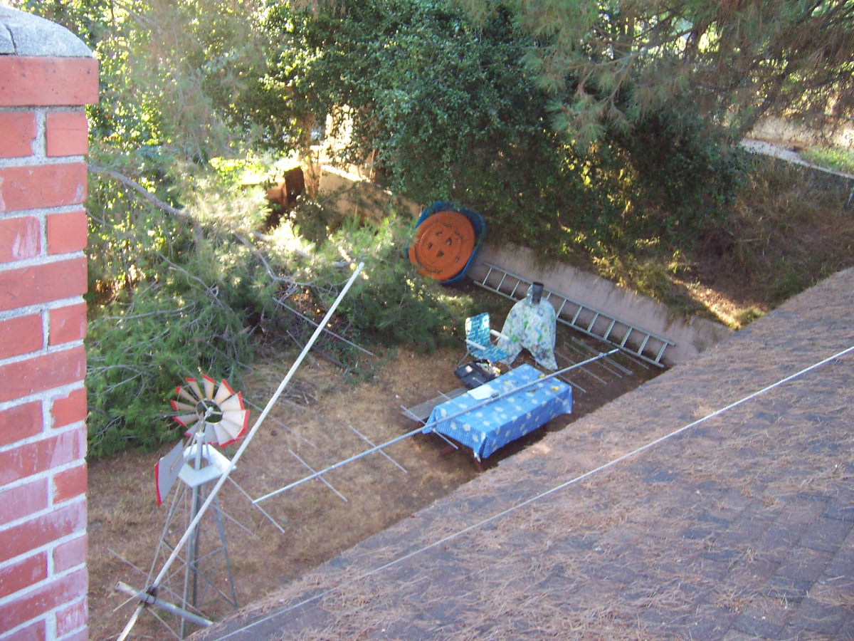
2005 Aug 17
New 2M12
beam arrives.
2005 Aug 21
Buy a 14 foot tree pruner at Orchard
Supply Hardware.
Trim around the discone.
Trim the new turning radius for the yet-unassembled 20 foot long beam.
2005 Aug 23
Measured 12.09 VDC at the module at full power output.
Reworked the DC supply cabling to the amplifier.
Now get:
Key Up: 13.20V with 4.95 bias
Key Down: 12.67V with 4.93 bias
No appreciable change in RF output.
Went ahead and swapped out the module under the following rule:
If it gets better, we're done.
If it gets worse, swap back.
If no change, done.
Retuned L1, L2, L4, and L5 (and rechecked L3) and got improvement back
up to "not significantly different from old module."
Re-dipped L3 to extinguish SWR light at 148.5 MHz into dummy load.
Tried various L1: 0 turn (short), worse; as specified; and plus
one turn, a few tenths of a watt better.
Bending coils together hurts, separating helps. Left "plus one"
in and peaked.
SWR light extinguished across the band on the dummy load.
The satellite beam is still broken, 5.0 forward, 1.9 reflected.
The discone loads like the dummy load.
2310 local. This is the end of the diagnostic rework on the
amplifier.
The 10C helped by 20%.
I no longer believe that using the wrong frequency slug means "mostly
erroneous on reflected."
I now believe, "mostly erroneous, for indication only."
I either have two modules (probably from the same batch) that are
slightly substandard (6.5 watts versus 7 watts spec.)
or I have an output circuit problem. All of the toroids and L1
have been
inspected and tweaked many times.
Note in the data sheets that 144 MHz is the low end of performance.
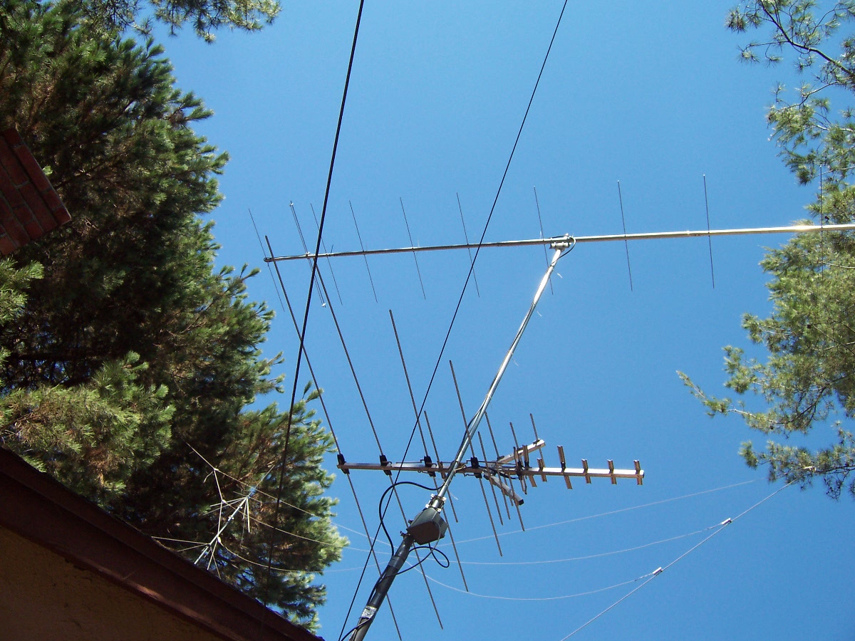
2005 August 27 Build and
install 2M12
replacing 2" O.D.
mast with
1-1/2".
2005 August 28 Remake the
rotator clamp U bolts correctly. ... in a
slight breeze.
2005 August 29 Order a KK7P
DSPx Module and KDSP10 Interface Adapter from TAPR. This is for the second
DSP-10.
2005 August 30
0324Z 8/31, Work KG6LUL, Lyle, 30 miles north of San Diego as first
contact on new beam. S6 to me, S7 to him (6 watt USB 144.230).
Do the "Fast PTT" mod while listening to Hurricane Katrina Health and
Welfare traffice on 3935.
Found the soldering iron still plugged in from last session.
Asked XYL (Viann, WD5EHM), "When was the last time I soldered
something?"
She said, "Last Spring?"
(... No, more like last Tuesday 8/23, but still, I've got to remember
to unplug that poor thing.)
Make appropriate notes in my schematic.
This is much better and
doesn't hang up the DSP-10 when accidentally PTT in CW mode.
2005 August 31
Re-measured power usage, output, and beam performance.
Brickette efficiency is 32% at nominal output.
1 dB compression point is around 3.3 watts.
The Bird 10C and dummy load are the trusted measurements.
DSP-10 levels interpolated from Figure 12. power measurement circuit
readings compared to extrapolated, fitted, Brickette values.
Inferred Brickette gain is 30.2 dB so the drive interpolations are low,
if anything.
Here are the "final" charts:
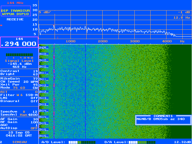
2005 September 10
0400 UTC Heard the Tehachapi Beacon on 144.294.5 sending 33 dits
and "DE N6NB/B DM05sb" Signal S-2, -140 dBm in -150 dBm
noise. Beam 340.
This is the first time I've ever heard anything to my north (and about
100 km north at that!) as I'm blocked by mountains that way.
Must be coming through the Grapevine (I-5 route north).
You can see the dit times and the ID times in the waterfall.
2005 Sept 10-12. Operated
the September ARRL
VHF
Test with
the new
beam and Fast PTT!
Made 33 QSOs in six grids: DM03, DM04, DM12, DM13, DM14, and CM94
from DM04. 198 points.
Won
the
Section!
See: ARRL
September VHF QSO Party Log. (This beats the 2-meter subset
30 QSOs in 4 grids from June test.)
Time limited, I decided not to operate other band/modes except for
DSP-10 on 2 meters linear (SSB).
CM94 is tough from here, not so much for the hundred mile distance due
to blockage from hills.
The new 2M12
beam made
a noticeable difference over prior antennas.
W7PUA is correct, this is not particularly a contest rig. It
overloads easily, and this would be worse in a better location or with
a preamp.
It is, however, clean, quiet, and sensitive and the filter options are
great. The "Fast PTT" was fun too.
And, I can copy the N6NB beacon in DM05 (see above) although I didn't
hear anyone operating the contest from up there.
2005 September
When my Astron RS-50M burped, I realized I had no backup 12 V supply in
the shack.
Acquired an MFJ-4035MV variable supply for bench testing and backup.
2005 September 19 around 0400 Z
heard local lightning on the
DSP-10. Unplugged everything!
2005 October 11
Used the new MFJ supply to make this plot.
- Vs measured with BK Test Bench 390
- Vcc2 measured with BK Test Bench 388A
- Po measured with Bird 10C
The OV led comes on at 14.75 on the way up and goes off at 14.48 on the
way down.
MFJ supply peaks out at 14.83 VDC with OV led on, but OV goes off key
down.
2005
November 22 Acquired a Mac
PowerBook G4 1.67 Ghz, OSX 10.4.3 and
Virtual PC 7.0. Began moving in.
2005 December 3
Determined that all amateur radio soundcard and
serial applications would work on the Mac under Virtual PC with a Keyspan USA-19HS
USB to serial adapter, except
for the DSP-10 loader and uhfa.exe. Looks like serial timing
problems.
2005 December 17 Upgraded
to UHFA / UHF3 version 3.50, put in a
PL of 131.8 and had a QSO with W4EF on WR6JPL on 147.750 / 147.150.
2006 January 21-22 Worked 20
stations in 6 grid squares (DM03, DM04,
DM13, DM14, CM94, DM12) in the ARRL
VHF
Sweepstakes using the same 2M12 beam
and 6 watt
brickette.
Didn't try as hard as before, have other things going on. Rig
works well for this, but did overload and go non-linear on one
local. Tried using TRLOG on the Mac through Virtual PC.
This was a disaster in half a dozen ways (doesn't set time right,
doesn't keep time right, doesn't do Cabrillo right). TRLOG is now
retired.
2006 January 22-23 Big
windstorm, gusts 50 - 80. JPL was
closed for the day Monday, some damage of JPL ARC antennas.
Worried about my 2M12
but it stayed up!
Through the winter did lots of 8 hour captures of screen at a very low
waterfall rate (1200) to see what kind of activity there was day to day
on various frequencies.
2006 May 10 Reading
through the operators manual systematically,
I came upon EME2 and got sidetracked for six weeks but, that's what
it's all about! Read all about it here:
EME2
Without Hardware Upgrades
In the process, discovered two things about the power output problems
above. 1) I had a two foot cable with 1.6 dB loss. No
longer. 2) There is ripple in the output power versus
frequency. Tuning around just a few KHz to get away from birdies
during EME
tests could make a
difference of a
watt or more, on the order of 1 dB. So, when choosing a lucky
frequency:
Status: Operational at 7.2 - 7.5
watts
2006 June 10 Operated the June ARRL contest.
Took a break to capture a moonrise pass (EME)
during the test. Was prevented from operating on Sunday but still
did as well as last year. What was great was that, as I worked on
EME2
post processing software, listening
to the
calling frequency
Monday and Tuesday evening after the test there was considerable
chatter among the locals about the weekend test. They were all
selling each other rigs, amplifiers, and antenna, shifting all the
equipment into new hands for "next time." Later, there was a two
hour QSO between a couple of guys who had been in the test. One
was
commuting home across the LA basin, the other was nearby and when he
got home went into the house and got on his rig there to continue the
QSO. The local contesting gossip was great. This is the way
I remember ham radio being! Maybe it still is the "good ol' days"
on some frequencies.
2006 June 19 Reading
Chapter 12.5 in Experimental
Methods
in RF Design about DSP-10 weak signal work and EME2 in
particular. Confirmed some of what I had figured out and learned
some new things as well.
2006 August 18 Upgraded
to UHFA / UHF3 version 3.80. Printed some new cheat sheets.
2006 September 9-10 Did
the September ARRL VHF QSO Party. See contest.
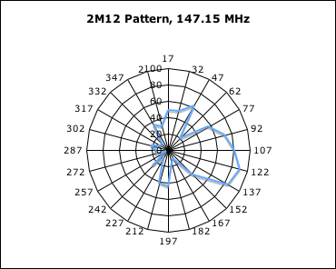
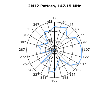
2006 September 23 Plotted
up antenna pattern data from last
summer.
On July 1, shuttle audio was being transmitted by W6VIO/R on 147.15
about four miles away. Beam heading to the repeater would be 99
true, but that direction is blocked by a hill. Apparently I see
mostly a reflection off of hills to our mutual south. During
quiet periods (carrier only) I took signal level measurements at beam
headings in 15 degree increments. Since my beam is misaligned,
(true - indicated = +17 degrees), the plots are calibrated in degrees
true running from 2 around to 347.
The left plot is in micro-volts and looks a lot like a beam antenna
pattern with maybe a little multipath to the left. The outer
circle is 100 micro-volts. The right plot is in dBm, a log
function of the left plot. The outer circle is -68 dBm. I
don't know the power output of W6VIO/R or what the path losses,
including the reflection, should be. Actually, these are signal
levels from a constant location source as the beam was rotated, so the
pattern is a mirror image of the beam pattern, for these
circumstances. Also, my best DXing direction is 120 indicated,
137 true, which points roughly towards San Diego. I think I see
the edge of the reflecting hill dropping off with increasing azimuth
from there.
2006 September 27 Took
some data with room temperature and
heated resistors and tried to use it to solve for DSP-10 noise
temperature. Got results that were consistent with 600 - 1000 K
(except one that was nonsense) but decided that I needed a better
designed experiment. Put some noise temperature reduction code
into the EME post processing software, then made a note to take it
out. The list recommended another approach. Back on the
todo list.
2006 October 6 Drove to
Foster City, Ca (San Francisco area) for
the AMSAT Symposium and Annual Meeting. Gave my paper Software Radios, an Enabling Technology
for Satellite, Space, and Ultra-Weak Signal Applications to goo
reviews on October 7. <Paper to be linked from here, from
Phase Five, and from EME of which it is a rewrite>. Driving
home October 8, we tried to work Echo from
the car using equipment we had with us. John, KG6HCO, operated
the 2 meter mobile rig at 65 watts and an FM HT on 70 cm while I
instructed verbally from the driver's seat roaring down I-5. We
heard a few squelch breaks (maybe) but were unsucessful.
Monitoring at home in future weeks, heard activity for several seconds
to a minute when Echo was overhead a few times. Need a better
antenna.
Took several more EME2 captures during September and October.
They have not been post-processed.
2006 December 19 0200 Z
Worked W6GL on CW, 144.200.600, 7
watts. Established contact on airplane scatter then it dropped
into the mud. Steve, WB2WIK on a hill between us (Chatsworth /
Woodland Hills) came in and intermediated. While he talked to
each of us, we listened for the other but heard little except for a few
more fortuitous airplane reflections. K6EMF/m La Crescenta also
came in.
2007 January 1 UTC.
Hooked up a straight key and called for SKN
contacts on 144.100 and 144.200. No responses. (Made a
conventional SKN contact on the 20 meter QRP frequency 14.060 on the
conventional TS-680 radio.) Did contact W6QE at 2007 January 2
0137Z on 144.200 CW but quickly moved to SSB.
2007 February 12 - March 11
In Hillsboro, Texas for my
mother's knee replacement surgery (bi-lateral means "both"). QRT
except for e-mail and a 40 meter Rockmite. Only had the Rockmite
on for a few days of one of the weeks. Heard some traffic
including W6GL calling me from California 2007 March 3, 0410 Z
(arranged by rapid e-mail exchanges), but antenna was not good enough
to be heard. Did some DSP-10 planning.
2007 May 12 Viannah,
KG6GXW, graduates from Franklin
& Marshall College
in Lancaster, Pa.
2007 June 22 Tried
installing DOS-only VPN from a Windows 98
disk. The disk is now unusable because I can't find the book with
the security code.
In the Windows 98 VPN I do have, edited autoexec.bat and added the line
'command.com' This causes it to boot up into DOS just like a
computer does but it still wouldn't load the DSP-10 via the
Keyspan. I think there is still a timing issue.
Using a dumb terminal program I can talk to the EZKIT through the
Keyspan (USB serial port) so I know the Keyspan is working in both
directions. This means it should be possible to write my own Mac
based (Xcode or Cocoa) loader.
Did not try EZSLOW because I already use EZFAST L which is already 9600
baud. It's handshaking, not bit sync that appears to be the
problem. Also, even after the DSP-10 is properly loaded, my
"resume" script doesn't work from this DOS-running window, so the
communication issue must exist there too. In both cases it
appears to get past the first step then wait forever for a second ack,
as if it hadn't started listening quite soon enough.
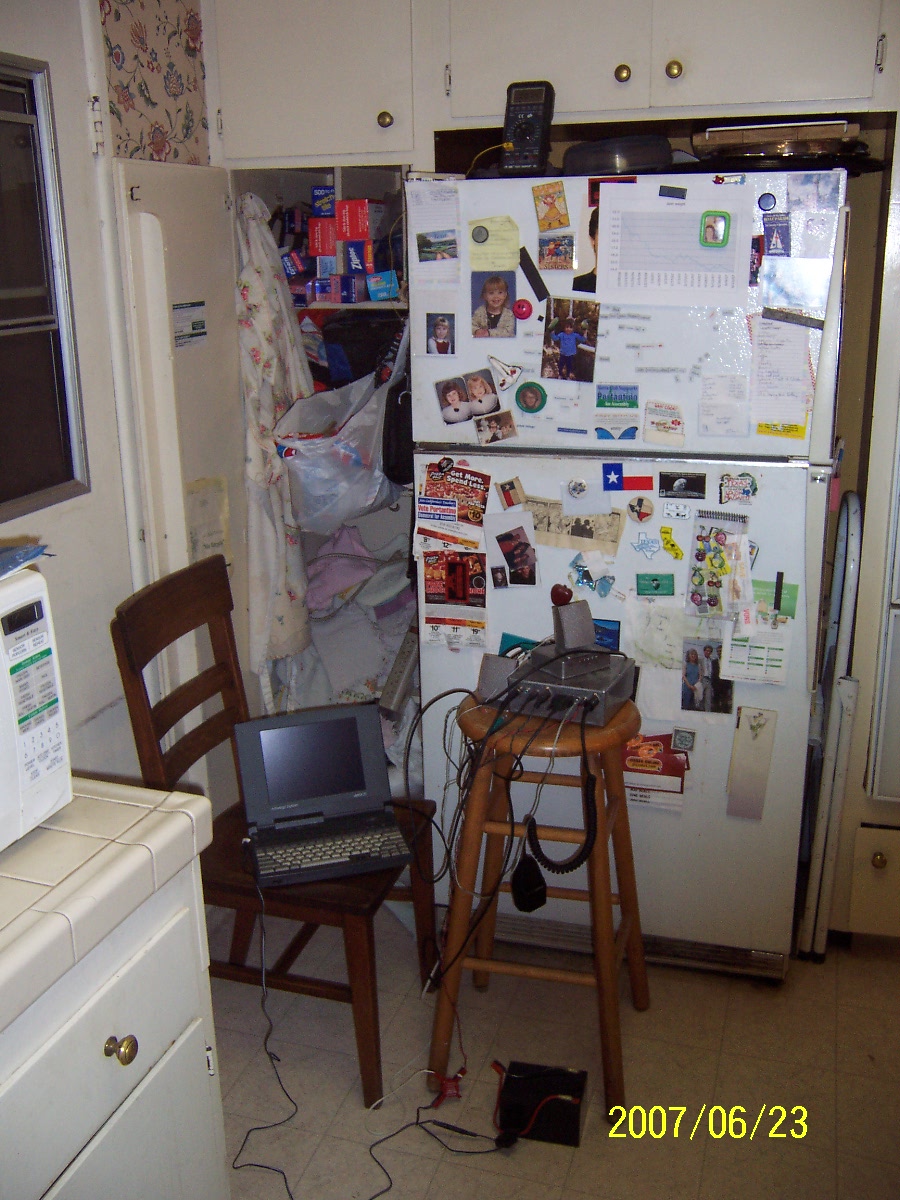
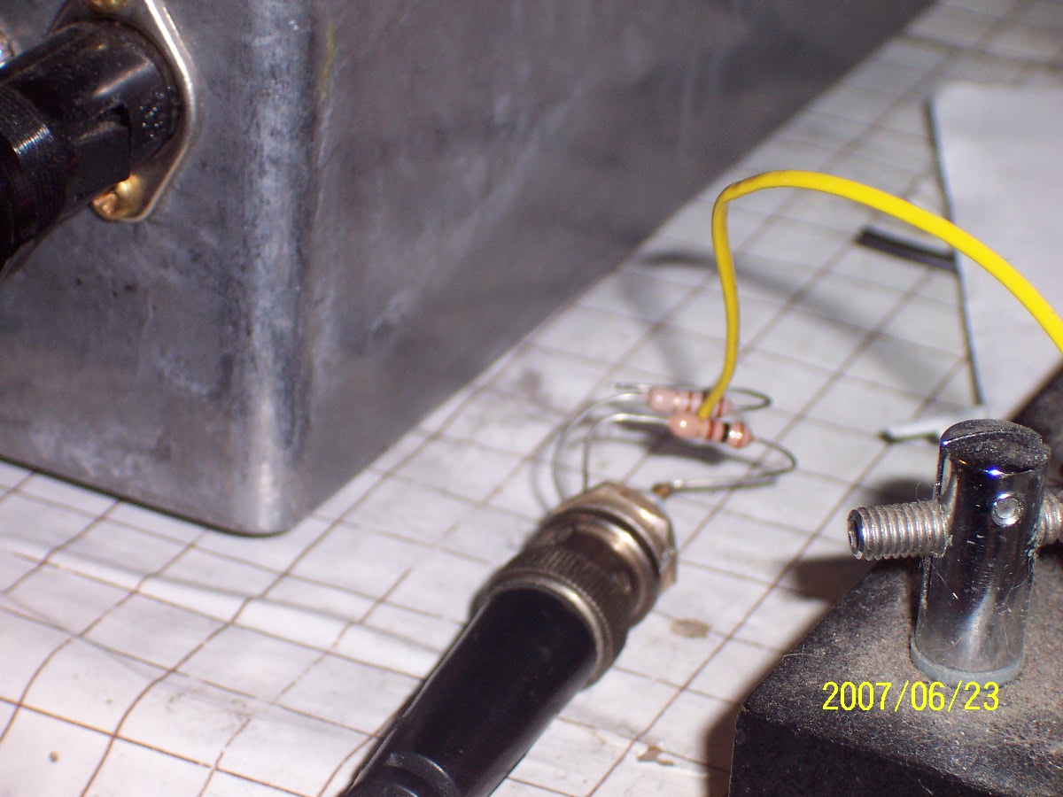
2007 June 23 Field Day
Bought a Radio Shack 350 watt inverter
and ran all needed computers, lights, and DSP-10 from a 75 AH storage
battery, either direct or via that convrter. Made 14 2-meter
phone (SSB and FM) QSOs in about six hours proving that the battery
would buy me plenty of time to lug the generator out and get it going
in case of disaster.
Detailed FD07 report:
I ran the whole office on my KWH battery (advertised at 75 AH / 12 V)
for 6-1/4 hours. Voltage was still 11.4 on rx and 11.1 on tx at
the "end."
No good indication of how far down I took the battery. I would
bet one of 1/4, 1/2 or 3/4 but really have no idea. What I do
know is that I can run everything over here (including the printer) for
at least six hours before I have to start messing with the
generator. That's the number I wanted. I'd bet 8 or even 12
hours in a pinch.
Good things about running with the 486SX/25 (ebay) laptop:
- it works at all
- works fine at ~11 V
Things that aren't as nice as I'm used to with the big surplus PC
(586/133):
- Keys up slow, sometimes a 3 second delay. Not good for
contesting!
- but sometimes instantly as expected
- Refreshes display slow. Probably an interaction with "keys up
slow."
- Slow to take keyboard inputs. Misses a lot of them altogether.
- painful reaches like for Alt F-10.
- No right Alt key! (Used for manual CW.)
- General abbreviated key set. Some keys are FN - something that
would be their own keys normally. (Yes, and no external keyboard
input.)
Well, ya get what ya pay for. Still it works at all and would be
fine portable or whatever.
General about the DSP-10.
As the designer says, it's not really a contest rig. Only one
roofing filter. Overload can cause digital saturation. This
doesn't happen when trying to detect echoes from Venus, but does happen
when your next door neighbor keys up his KW. CQ FD! CQ FD!
It's generally a do it yourself, futz around rig, not a contesting
setup with a thousand individualized programmable controls. Two
of them would be kinda cool, however. Someday.
No trouble running the rotator from the inverter. While I was at
Radio Shack I also got a mast mounted TV preamp. Now I can watch
KCET digital! (But two meters trashes it.)
2007 June 24 0330 - 0700
Z Took extensive room-temperature and
load-in-the-freezer noise data on DSP-10 in a new attempt to measure
noise temperature. See 2007 September 12 for data reduction.
Cold -- resistors in the freezer ~
254K.
Warm -- room temperature, thermocouple between 100 ohm resistors in
parallel ~297K.
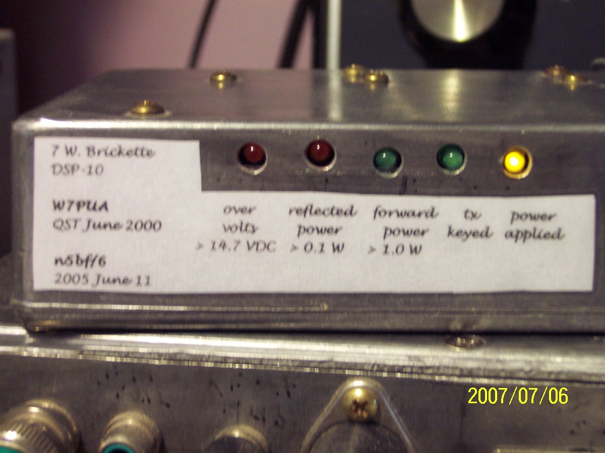
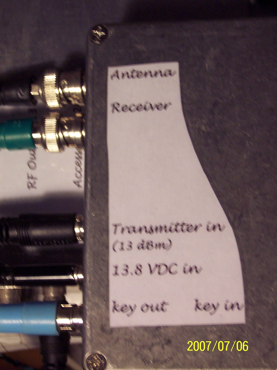
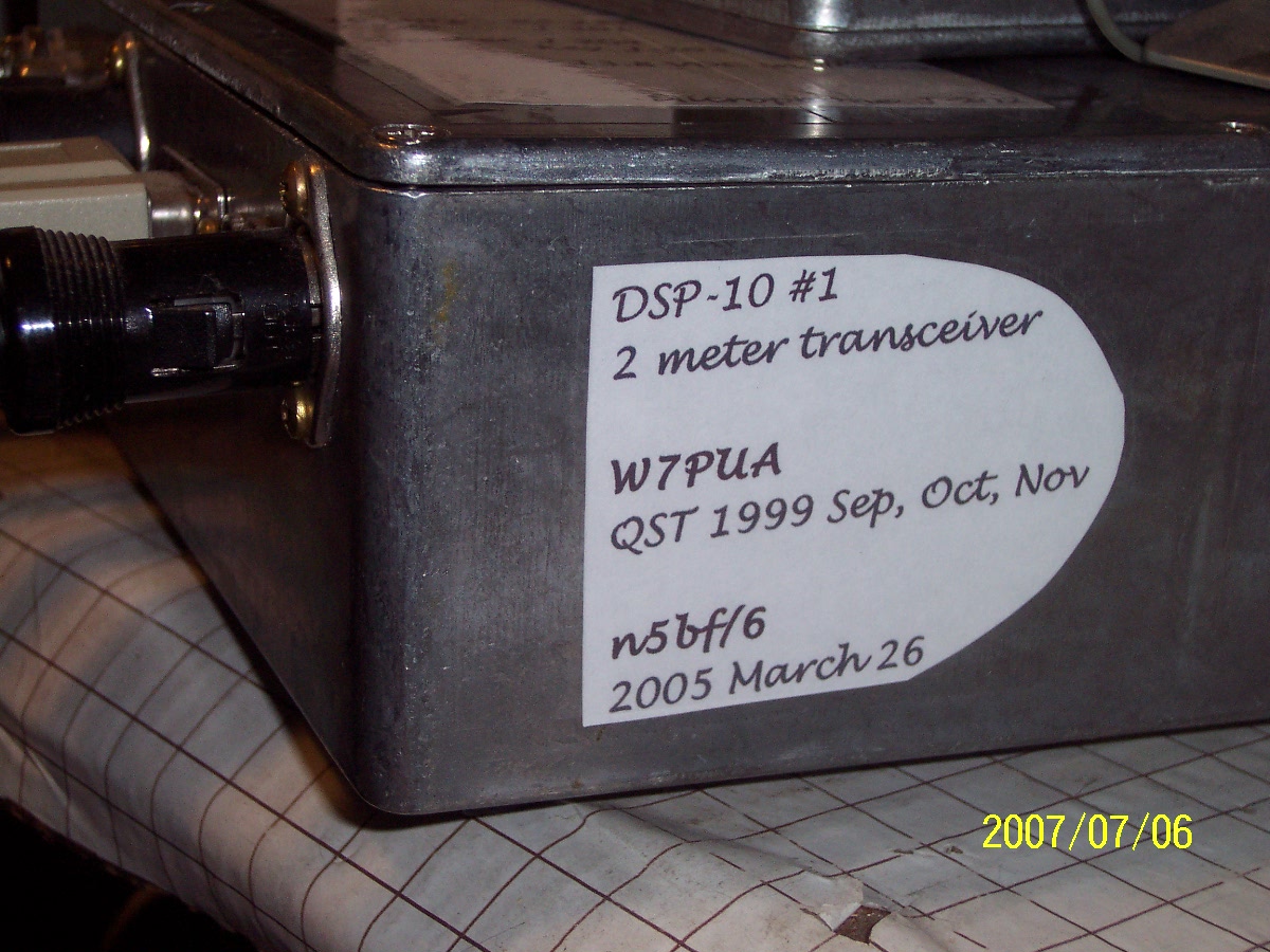
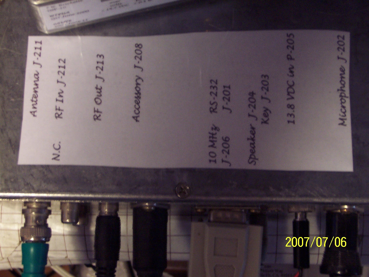
2007 July 5
Box Labels --
The hard part was selecting the font.
2007 July 7 Took DSP-10
filter data.
2007 August 17 0353 Z.
WF6A DM14, Bill in Azusa, called CW CQ on
144.200.700. Had a 20 minute CW QSO. Marked my
"worked/heard on frequency" list at "8/98", that is, heard 98 calls of
CQ or ID that were eligible for me to attempt QSOs, answered and
completed 8. Utilization goal is a 1/10 ratio of worked to heard.
2007 August 20 and
2007 September 1. These
are Excel plots of some filter
ripple data I took on 2007 July 20. Posted questions to the list
about these.
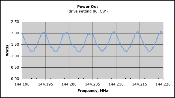
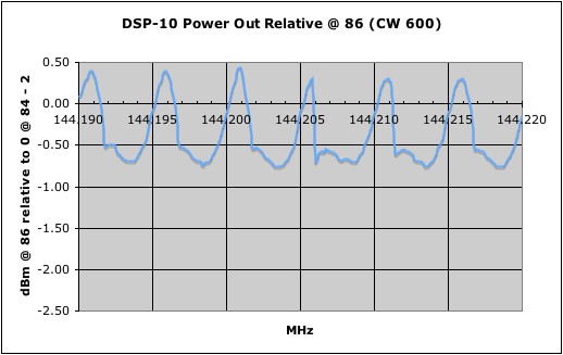
Power output was taken every 100 Hz using the Bird 10-C slug and a 50
ohm dummy load. Three things are notable. It looks like the
5 KHz 1st L.O. synthesizer switching may cause the bumps around
144.196, 144.201, 144.211, etc. Second, this seems like more
ripple than expected. Here is the same data in a log plot.
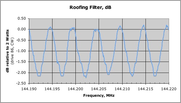
Note that the ripple is a little over 2 dB. I think this is six
repeats of a 5 KHz piece of the passband of the 19.665 MHz four crystal
filter. Normal ripple in a passband is usually limited to 1 dB by
design, but I may be seeing a passband edge here.
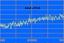
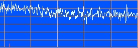
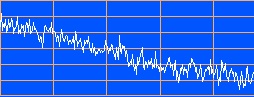
Here is the corresponding information seen as receiver noise looking
into a dummy load. The vertical scale is 1 dB per division.
I would call the difference between the trough and peak levels at
144.202 and 144.205 about 2.5 dB. These were taken as three
snapshots about a minute apart at averaging rate 102.
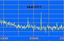
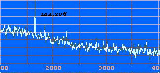
This is comparable to a set of W7PUA data taken similarly which can be
seen at http://www.proaxis.com/~boblark/p527xfil1.gif.
His 19.665 MHz ripple is more like 0.5 dB. (I also have a few "in
box" birdies that Bob doesn't have.)
There may be some sensitivity to this in the settings of L12 and L13
(See schematic QST
1999 September p. 37. Figure 4.). I remember from the initial
alignment that transmitted power output or received noise wasn't very
sensitive to those inductors. Displays like this could be used to
tweak those cans in (near) real time if they affect flatness. I'm
not going to do anything about this now but will add a note in Planning that this might help
smooth things out if a flatter response is needed for some future
project. This filter and its response are discussed in the QST
reference, Figure 5.
Third, you can see some trending in the peaks. Noting this, I
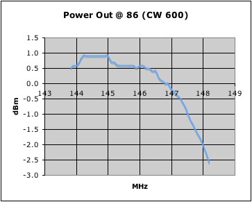
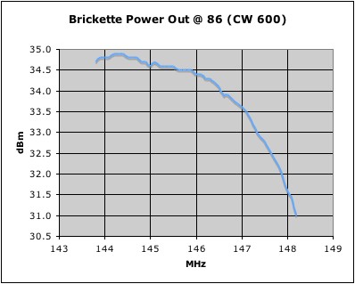
swept the whole band. In this next plot I took data every 10 KHz
(on what was the same 5 KHz sub-frequency so as to miss the 19.665 MHz
effect) from 143.8 to 148.2 (into the same dummy load of course).
I have good synthesizer lock over a larger range but didn't think there
was much to prove by extending any further out of the ham band.
You can clearly see that, during the alignment, it was peaked for 147
MHz and you can see why, because it drops off at higher frequency
faster than at lower. I'm wondering, however, if I should repeak
for 146.0 or 146.5 in order to get better performance at 144.0 - 144.3
where most of the interest here is.
This looks very much like the top of the response curve for the
four-pole interstage filter discussed at QST 1999
September, p. 36. Figure 3. but I notice that in that plot the low
end roll off is around 6 dB per MHz whereas mine from 145 to 144 is
more like 3 dB per MHz. If I'm on the edge of the slope, I'm
barely on the edge. Another note for Planning.
When I initially characterized
the rig, I decided that a power setting of 82 gave one watt out of the
Brickette. I now see that this was highly dependent on the
frequency chosen for the measurement. Up in the FM band, I get
one watt at setting 80. At 144.200 it needs 83.
2007 September 12
Processed the noise figure data taken
on June 24. It is all garbage.
Experiment design. Take ten one-minute noise integrations (4800
Hz Non) writing these down with the time and the temperature in
Fahrenheit (which has higher resolution than Centigrade) in each of the
following cases:
A: 144.150 MHz 50 ohm
B: 147.540 Mhz 50 ohm
C: 144.150 MHz 50 ohm, through Brikette
D: repeat A
E: 144.150 MHz 100 ohm.
Per case, ten points cold (load resistor on the end of the antenna coax
in the freezer), ten points warm (room temperature in the shack.)
The calculation: ( Tr + T2 ) / ( Tr + T1 ) = P2 / P1
Solve for Tr
For R = P2 / P1 = 10^( ( dB2 - dB1 ) / 10 )
Tr = ( T2 - R*T1 ) / ( R - 1 )
Wrote a C++ program "noiseFigure" to convert the F to Kelvin and
perform this calculation for every pair of numbers in each test (100
comparisons) and to cross compare cases A and D, that is, A cool versus
D warm and A warm versus D cool. Anticipated the need to do
statistics on the results to get a good answer.
Results: All tests and all test points produced nonsense.
(See also http://pages.cs.wisc.edu/~kovar/hall.html
.)
Discussion.
In the above equation if R > T2/T1 or if R < 1, a negative answer
will result. This is clearly wrong. In my data, T2 / T1 is
about 295 / 254 (Kelvin) which is about 1.16. That's about 0.6
dB. Meanwhile, due to the experiment setup, doing warm and cold
in different locations, for example, the differences between cool and
warm data sets were 2 or even 3 dB. This is large when the signal
is supposed to be 0.6 dB.
The fundamental problem here is that T2 / T1 ~ 1.2 isn't enough signal
to work with unless you have 0.01 dB accuracy and stability in the
measurements and the test setup, which we don't.
Use of the "Y Method," a different arrangement of the same calculation,
produces similar nonsense.
Y = 1 + ENR / Ftot, so noise figure Ftot = ENR / ( Y - 1 )
Expected ENR in this case is 0.2. If Y > 1.2, noise figure is
less than unity, that is, less than 0 K.
Suddenly, I understood what a "calibrated noise source" is all
about. A typical noise source used for a measurement like this
puts out 7000K. I think I'll acquire a noise source and replan
the experiment rather than working on ways to heat a resistor up to
7000K (hotter than the surface of the sun!).
2007 September 12 0509 Z
Thought I was seeing the KH6 beacon in
an LTI on 144.170 at beam heading 267 indicated (250 true). It
was too perfect, however. It was on 500 Hz audio when showing
144.169.500. I know that my reference oscillator is high, so I
expect the signal to be below that, but I don't know its exact
frequency. Doing the same LTI on the dummy load gave the same
little peak so its a birdie in the radio.
2007 December 15 Performed the
long-awaited re-peaking of
the RF (144-148 MHz) and 1st IF (19.665 MHz) to reduce
roofing filter ripple and generally get more power output and
sensitivity at the low end of the band, 144-146, where the weak signal
action is.
First I spent half an hour looking for a proper tweaking tool and finally
settled on the only object in the house that would turn the little
slugs, a metal eye-glasses screwdriver, an improper tweaking tool.
Marked this with a tape flag so as to accurately count turns.
Terminated the antenna port, set the spectral display to the 7 Hz range
and tried for a while to make adjustments based on readings of the
noisy noise curves. Decided fairly quickly that this was hopeless
and unscientific. Pulled out my new KA7EXM power meter
and made tables of
power output readings for Xmit Pwr 80 at 144.200, .201, .202, .203,
.204, and .205. Because of the LO switching, .200 and .205 were
expected to match, being through the same part of the IF at the
different LO settings. For each set of measurements, I looked at
the peak-to-peak change. With the original settings, as seen in
"Roofing Filter, dB" above, peak-to-peak was over 2 dB. Working
first with L12, I moved one turn each direction and remeasured.
From the best (least peak-to-peak change) of those three, I moved +/-
half a turn, remeasuring, then +/- a quarter turn. From the best
of these, I then repeated this at L13. From the best combination
of L12 and L13, I moved L12 again, then L13, remeasuring each
time. (Yes, like tuning a pi-network, which this is, but lots
slower.) After a couple dozen readings like this, I had settled
on L12 at +1.0 turns and L13 at +1.25 turns from the original
settings. The metal screwdriver doesn't matter for this because
it is removed while measurements are taken.
Those original settings were made during the first alignment where the
whole chain was peaked by ear and S-meter readings near 147 MHz.
I remembered this being straightforward at RF but that the IF coils,
L12 and L13 didn't make much difference. Now, with improved
equipment and understanding of what was going on, I could do a better
job at IF. These settings gave peak-to-peak of about 1.0 dB, a
big improvement. I do not know if I have found a local or global
minimum.
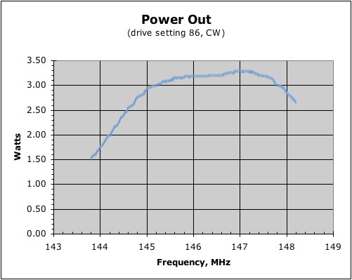
Next, I went to the RF chain, L8, L9, L10, and L11, to get better
performance at the low end of the band than is shown in "Power Out"
above. First I reconfirmed by taking points every 500 KHz from
144 to 148 MHz that the shape of that curve was still pretty much the
same as before. This showed a difference of 4 or even 5 dB
between 144 and 147 MHz power output. Next, at 147.0 I
transmitted into the power meter and peaked each coil in turn using the
metal screwdriver. Each coil changed by a significant fraction of
a turn. Finally, when somebody started talking on the Catalina
repeater (147.09, 30 miles away) I repeaked L1 and L2 by ear (receive
path only), confirming that they had an effect, but not making much net
change.
When I remeasured every 500 KHz across the band, it was much flatter
now than before, with some possible roll off at the high end rather
than the low end.
Went back and did another dozen iterations on L12 and L13, this time to
1/8th turn resolution, about the best I thought I could
reliably do, and found new settings (a little surprising, indicating
interaction between RF and IF filters) at +0.75 and +1.0 turns for L12
and L13 respectively. The final IF sweep showed ripple at 0.6 dB,
at least from my coarse KHz measurement.
I called this done and put the lid back on.
Then, made the following plots which are designed to be comparable to
those above so the improvement (or at least the change) can be easily
seen. These are not exactly the same. The plots above were
made with the Bird wattmeter and inferences. These were made with
the KA7EXM low power wattmeter, freshly calibrated.
First, drive linearity. These compare to plots from 2005 August
31, near the top of this page.
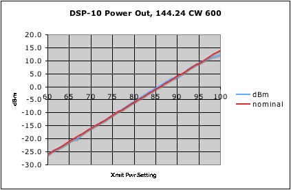
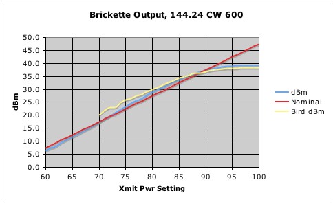
In the barefoot plot (right) there is a little saturation happening
above 96-97. The Brickette version shows why it isn't very useful
to use Xmit Pwr over 95.
The barefoot plot was made with the DSP-10 transmitting directly into
the power meter. For the Brickette, the amplifier output goes to
the Bird wattmeter (10C) then to the 40 dB tap which drives the power
meter, then to a dummy load.
Amplifier performance parameters from this data are:
Gain: 33.4 dB (even higher than previously thought, uncertainty
in the measurement is around 1 dB).
1 dB compression point: ~ 4 Watts, setting 89.
Power Max: 7.0 measured by Bird 10C, 8.1 measured by the KA7EXM
meter.
As we will see next, this could have been 0.4 dB, half a watt higher,
if I'd used a slightly different frequency. The part spec. is 7
watts, so I'm convinced now that it is all working right.
Next we consider ripple in the IF filter.
This compares directly to the 2007 September 1 "Power Out" plot above
in terms of rig settings and plot scales. Note that the
frequencies of the peaks and valleys have moved and that the
peak-to-peak is about 1 dB, significantly less than before. There
is something going on in the values around 144.206 and 144.211 that has
something to do with the LO switching algorithm. These were taken
using the KA7EXM power meter "relative" mode just for the fun of it.
This plot shows six sweeps across the IF passband of interest.
Now we look at this same behavior in the received spectrum.
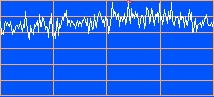
.198
.200
.202
.204
This is an enormous improvement over the same plot above and looks
exactly like http://www.proaxis.com/~boblark/p527xfil1.gif
when you realize that Bob's plot is 2 dB/division and this one is 1
dB/division. We have the same high end IF roloff (actually, low
end in the IF).
The transmit and recieve measurements are consistent. This is
much better than before.
(Note: I used a different 6 KHz than above in order to stay out
of a nasty internal birdie just above 144.205.)
Finally, RF broadband behavior.
I would have preferred to have it a little flatter across the entire
band, but since 144-146 looks good, the higher frequencies are FM where
0.1 dB is less important, and other uses of those frequencies will
likely be through transverters that will have a little slack of their
own, I think I can leave it alone for now.
The fact that I peaked for 147 MHz and got this which is 2-3 MHz lower
is due to using the metal tool in real time peaking/measuring.
Amplifier gain from this data is 33.8 +/- 0.2 dB.
The spectral display where I usually listen, 144.0 - 144.3, is much
flatter to look at now and the noise level is a few dB higher.
These are pleasing results. Maybe I can do EME2 in only 5000
points now.
2008 June 6 - QSO with W6GL/m
John, W6GL did some contract work at JPL for a few years.
He would usually leave work late, after I was at home and his route
went right by my house near the freeway. So, he put a 2 meter SSB
rig in his truck and we had some QSOs, like this one:
You can see him at 0255 Z (1955 local) hitting 60 over 9 and
overloading the front end, then continuing down the freeway getting
weaker and weaker. The scrolling stops when I'm talking.
Eventually (off screen) he would get to the Santa Sussanah pass on the
way into Simi Valley and we'd lose contact.
2008
September 6 - Establish DSP-10
Noise Figure.
Reread the 2007 September 12 discussion (see
"nonsense" above), then unboxed the newly calibrated noise source
(see Test
Equipment for 2007 December 20 through 2010 May 15) to try it
again. Dug out my old files with all the materials about noise
measurement and noise sources and found them coated with a fairly thick
layer of dust.
Reread the QST 1994 May p. 37 article and did the following algebra:
Y = Non / Noff = ( F + ENR ) / F = 1 + ENR / Ftot
Ftot = ENR / ( Y - 1 ) = ENR / ( Non/Noff
- 1 )
Also T = ( F - 1 ) * 290K once F is known.
Took several data points through a nice set of JFW Industries
attenuators but a questionable 6 foot BNC hookup cable and made the
following calculations:
DSP-10 test @ 144.99.700 USB, 60
second measurements.
Non Noff Attn
Pon Poff F
F dB K
42.208
29.92 0 16626
982 15.84 12.00
4302
39.330
29.85 3
8570 965 16.05
12.05 4363
36.745
29.54 6
4726 899 14.90
11.73 4031
33.850
29.64 10
2427 920 15.42
11.88 4182
30.103
29.48 20
1024 886 16.21
12.10 4411
Through Brickette, 875, and Bird
43
41.525
29.24 0
14207 839 15.85
12.00 4306
The first measurement agrees well with the 13.4 dB ENR measurement I
made when the source first worked (see Test
Equipment for 2008 April
8).
The last measurement demonstrates that losses through the amplifier's
receive paths, are not significant.
Having expected 600K to 1000K, I was surprised by this 4300K
result. Posted to the DSP-10 list.
Mike KD7TS reported that his DSP-10 had a noise figure of 11.5 dB,
which was fine since he used it as a 10 GHz IF. Based on the
measurements with all the attenuators and this one independent expert
confirmation, I decided the measurement was accurate enough and I
decided that, three years of successful on-the-air
operation and QRPpp
EME2 notwithstanding, I really needed a good preamp in front of
this rig. Also on the list, Scott N0EDV suggested on of the Down
East Microwave kits at http://www.downeastmicrowave.com/Catalog.htm#BM2M.
Hooked up to the TS-680. With the preamp on (18 MHz and
above) "on" goes to S-3 while "off" is S-0, no meter movement.
Cannot make conclusions about noise figure from this information except
to note that it is a few thousand K.
2008 October 11 - System Measurements
with new Preamp
case
K dB
DSP-10 alone
3200 10.8 *** better than measured on 2008 September
6. Possibly because this is a good jumper cable.
system
71 0.95
preamp
only 51 0.7 inferred from
amplifier chaining equation, but exactly as advertised
station 200
2.2 estimated, based on 1.5 dB cable loss to antenna
Station improvements are detailed in Phase Four.
n5bf/6
DSP-10
page
n5bf-at-amsat-dot-org
updated 2008 October 29, 2010 March 26, 2010 December 18, cbd